3
Installing Cables
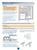
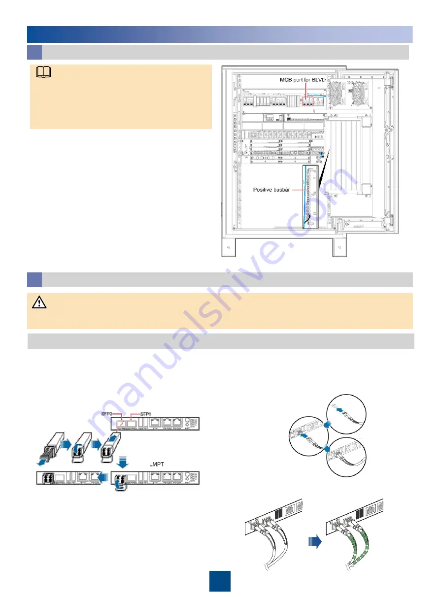
1. Connect the 3V3 connector at one end of
the BBU power cable to the
-48 V
port on the
UPEU module of the BBU, and tighten the
screws on the connector to 0.25 N·m.
2. Connect the other end of the BBU power
cable to the TP48200A cabinet.
a) Connect the cord end terminal to the
BLVD 16 A MCB port
F6
.
b) Connect the OT terminal of the BBU
power cable to the positive busbar of the
TP48200A.
Installing a Power Cable
b
Connecting Ethernet Cables or Optical Fibers to the Main Processing Board
c
a
3. Bind the cables properly using the optical fiber
binding strap based on BBU cable claw positions.
c1 Installing an FE/GE Optical Fiber
1. Lower the puller of an optical module and
insert the optical module into the
SFP0
/
SFP1
port on the LMPT, the
FE/GE1
port on the
UMPTb2, or the
XGE1
/
XGE3
port on the
UMPTe3. Then, raise the puller.
2. Remove the dustproof cap from the optical
fiber. Connect an FE/GE optical fiber to the
optical module.
4. Install the winding pipe at the end of the
optical fiber. Ensure that the winding pipe is
installed at the position between the optical fiber
connector and the first optical fiber binding point.
NOTICE
Connect Ethernet cables or optical fibers to the UMPT/LMPT based on actual requirements. Cable layout for Ethernet cables
and optical fibers is identical.
Here is the process of installing a BBU power
cable in the TP48200A cabinet. For details about
how to install a BBU power cable in other
scenarios, please see
“Installing a BBU Power
Cable” in
eNodeB Product Documentation.
NOTE

