background image

FusionModule1000A40 Prefabricated All-in-One Data 
Center 
Commissioning Guide 

4 Preparations for Power-On Commissioning 


Issue 02 (2019-12-20) 

Copyright © Huawei Technologies Co., Ltd. 

19 


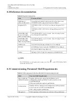
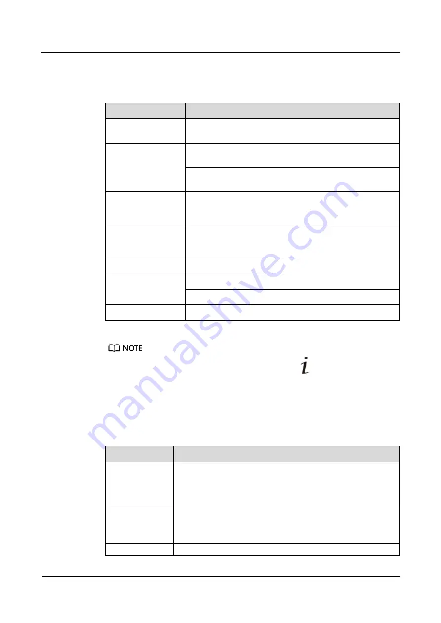
4.2 Reference documentation 

Table 4-2


Required documentation 

Item 

Document Name 

Prefabricated 
all-in-one data center 

FusionModule1000A40 Prefabricated All-in-One Data Center 
V200R003 Initial Configuration Parameter Manual


Integrated UPS 

UPS5000-E-(50 kVA–125 kVA) User Manual (Integrated UPS 
3.0)


UPS5000-E-(20 kVA–80 kVA) User Manual (Integrated UPS, 
208 V)


NetCol5000-A025 
In-row Air Cooled   
Smart Cooling Product 

NetCol5000-A025 In-row Air Cooled    Smart Cooling Product 
User Manual (300 mm Width)


NetCol5000-A021 
In-row Air Cooled   
Smart Cooling Product 

NetCol5000-A021 In-row Air Cooled    Smart Cooling Product 
User Manual (208 V)


Outdoor unit 

NetCol500 Variable Speed Outdoor Unit User Manual


ECC800 

ECC800 Data Center Controller V100R003C00 User Manual


ECC800 V100R001 Alarm Reference


NetEco 

iManager NetEco Product Documentation-(V600R008C20)


The ECC800/NetEco version depends on the version in use. Click 

  on the ECC800/NetEco WebUI 

to obtain the current version. 

4.3 Commissioning Personnel Skill Requirements 

Table 4-3


Skill requirements for the FusionModule1000 commissioning personnel 

Field 

Personnel Skill Requirement 

Power supply and 
distribution system 

Familiar with the power supply and distribution system 
configurations and the operations for each core device in the 
FusionModule1000 

With power distribution engineer qualifications 

Cooling system 

Familiar with the cooling system configurations and the operations 
for each core device in the FusionModule1000 

With cooling engineer qualifications 

Management 

With knowledge in the hardware and software of the prefabricated 

Summary of Contents for V200R003C10

Page 1: ...FusionModule1000A40 Prefabricated All in One Data Center V200R003C10 Commissioning Guide Issue 02 Date 2019 12 20 HUAWEI TECHNOLOGIES CO LTD ...

Page 2: ...tomer All or part of the products services and features described in this document may not be within the purchase scope or the usage scope Unless otherwise specified in the contract all statements information and recommendations in this document are provided AS IS without warranties guarantees or representations of any kind either express or implied The information in this document is subject to c...

Page 3: ...ce This document is intended for Maintenance engineers Technical support engineers System engineers Commissioning engineers Symbol Conventions The symbols that may be found in this document are defined as follows Symbol Description Indicates a hazard with a high level of risk which if not avoided will result in death or serious injury Indicates a hazard with a medium level of risk which if not avo...

Page 4: ...ortant information in the main text NOTE is used to address information not related to personal injury equipment damage and environment deterioration Change History Changes between document issues are cumulative The latest document issue contains all the changes made in earlier issues Issue 02 2019 12 20 Updated the safety information Issue 01 2019 07 15 This issue is the first official release ...

Page 5: ... Tool Preparations 17 4 2 Reference documentation 19 4 3 Commissioning Personnel Skill Requirements 19 4 4 Preparing for the Power Supply and Distribution System Power On Commissioning 20 4 5 Preparing for the Cooling System Power On Commissioning 21 4 6 Preparing for the Management System Power On Commissioning 22 4 7 Preparing for the Fire Extinguishing System Power On Commissioning 23 5 Check B...

Page 6: ... 8 3 2 1 Setting iBOX and iBAT Parameters 78 8 3 2 2 Networking iBOXs and iBATs in Wireless Mode 79 8 3 3 Commissioning Access Control Components 80 8 4 Optional NetEco Management 81 8 4 1 Basic Operations Before Adding Devices 81 8 4 1 1 IP Address Preinstallation Planning 81 8 4 1 2 Obtaining the NetEco Software License 81 8 4 1 3 Powering On a Server 82 8 4 1 4 Logging In to the PowerEcho 82 8 ...

Page 7: ...Registering with the OCX Plug in 104 8 4 4 1 5 Adding a Camera Using Automatic Discovery 107 8 5 Commissioning Fire Extinguishing Devices 108 8 5 1 Commissioning Fire Extinguishing Devices Standard 108 8 5 1 1 Commissioning the Fire Alarm Control Panel standard 108 8 5 1 2 Commissioning the Emergency Lights standard 111 8 5 2 Commissioning Fire Extinguishing Devices CE 112 8 5 2 1 Commissioning th...

Page 8: ...ing operating or maintaining the equipment The safety instructions in this document are only supplements to local laws and regulations Huawei will not be liable for any consequences of the following circumstances Operation beyond the conditions specified in this document Installation or use in environments which are not specified in relevant international or national standards Unauthorized modific...

Page 9: ...ling a conductor surface or terminal measure the contact point voltage and ensure that there is no risk of electric shock After installing the equipment remove idle packing materials such as cartons foam plastics and cable ties from the equipment area In the case of a fire immediately leave the building or the equipment area and turn on the fire alarm bell or make an emergency call Do not enter th...

Page 10: ...pment with scratches cannot be exposed to an outdoor environment for a long period of time Before operations ensure that the equipment is firmly secured to the floor or other solid objects such as a wall or an installation rack Do not use water to clean electrical components inside or outside of a cabinet Do not change the structure or installation sequence of equipment without permission Do not t...

Page 11: ...ns and are clear of the sources and degree of various potential hazards in equipment installation operation maintenance Trained personnel personnel who are technically trained have required experience are aware of possible hazards on themselves in certain operations and are able to take protective measures to minimize the hazards on themselves and other people Operators operation personnel who may...

Page 12: ...uting cables ensure that a distance of at least 30 mm exists between the cables and heat generating components or areas This prevents damage to the insulation layer of the cables Do not route cables behind the air intake and exhaust vents of the equipment Ensure that cables meet the VW 1 flame spread rating requirements Bind cables of the same type together When routing cables of different types e...

Page 13: ... Environment Requirements To prevent fire due to high temperature ensure that the ventilation vents or heat dissipation system are not blocked when the equipment is running Install the equipment in an area far away from liquids Do not install it under areas prone to condensation such as under water pipes and air exhaust vents or areas prone to water leakage such as air conditioner vents ventilatio...

Page 14: ...to warn away irrelevant personnel Carry the operation machinery and tools properly to prevent them from falling off and causing injuries Personnel involving working at heights are not allowed to throw objects from the height to the ground or vice versa Objects should be transported by tough slings hanging baskets highline trolleys or cranes Ensure that guard rails and warning signs are set at the ...

Page 15: ... that it is intact and confirm its load bearing capacity Do not overload it Ensure that the ladder is securely positioned The recommended angle for a ladder against the floor is 75 degrees as shown in the following figure An angle rule can be used to measure the angle Ensure that the wider end of the ladder is at the bottom or protective measures have been taken at the bottom to prevent the ladder...

Page 16: ... be aware of unstable or heavy objects on the cabinet Be cautious to avoid injury when moving heavy objects When moving the equipment by hand wear protective gloves to prevent injuries Move or lift the equipment by holding its handles or lower edges Do not hold the handles of modules such as power supply units fans and boards that are installed in the equipment because they cannot support the weig...

Page 17: ...sure components such as the compressor and refrigerant pipe to prevent the refrigerant system from being cracked or exploded due to misoperations Refrigerant Frostbite Refrigerant leakage may cause frostbite Take protective measures for example wear antifreeze gloves when handling refrigerant Storage and Recycling Do not store devices near a heat source or under direct sunshine Keep devices away f...

Page 18: ...ns for battery handling and master the correct battery connection methods Do not expose batteries at high temperatures or around heat generating devices such as sunlight fire sources transformers and heaters Excessive heat exposure may cause the batteries to explode Do not burn batteries Otherwise the batteries may explode To avoid leakage overheating fire or explosions do not disassemble alter or...

Page 19: ...e polarities when installing batteries Do not short circuit the positive and negative poles of the same battery or battery string Otherwise the battery may be short circuited Check battery connections periodically ensuring that all bolts are securely tightened When installing batteries do not place installation tools on the batteries Battery Short Circuit Battery short circuits can generate high i...

Page 20: ...ribed in this section There is a risk of explosion if a battery is replaced with an incorrect model A battery can be replaced only with a battery of the same or similar model recommended by the manufacturer When handling a lithium battery do not place it upside down tilt it or bump it with other objects Keep the lithium battery loop disconnected during installation and maintenance Do not charge a ...

Page 21: ...nologies Co Ltd 14 Exercise caution when manually shutting down the UPS inverter for transferring to bypass mode or when adjusting the UPS output voltage level or frequency Doing so may affect the power supply to equipment Exercise caution when setting battery parameters Incorrect settings will affect the power supply and battery lifespan ...

Page 22: ... the reliable running of all systems Improper modifications of parameters may cause abnormal running status or even damage to the systems The initial parameters of the FusionModule1000 are configured before delivery For details about how to modify the parameters see the documents delivered with the devices and the actual solution configuration Prior to the power on commissioning remove all the pro...

Page 23: ...sioning Guide 3 General power on commissioning process Issue 02 2019 12 20 Copyright Huawei Technologies Co Ltd 16 3 General power on commissioning process Figure 3 1 shows the general power on commissioning process Figure 3 1 General power on commissioning process ...

Page 24: ...awei Technologies Co Ltd 17 4 Preparations for Power On Commissioning 4 1 Tool Preparations Table 4 1 lists the tools required for power on commissioning Table 4 1 Tools Tools Phillips screwdriver Flat head screwdriver Utility knife Multimeter Electroprobe Network cable tester Cable tie Insulation tape Marker ESD gloves Step ladder 2 m ESD wrist strap ...

Page 25: ...RJ45 crimping tool Wire stripper Flashlight Hand held thermometer Heat shrink tubing Phase sequence meter Clamp meter Insulation megohmmeter Point thermometer This table may not list some tools required at specific sites Onsite installation personnel and technical support personnel should prepare tools based on site requirements Some dedicated tools and installation materials provided with the equ...

Page 26: ...oduct User Manual 208 V Outdoor unit NetCol500 Variable Speed Outdoor Unit User Manual ECC800 ECC800 Data Center Controller V100R003C00 User Manual ECC800 V100R001 Alarm Reference NetEco iManager NetEco Product Documentation V600R008C20 The ECC800 NetEco version depends on the version in use Click on the ECC800 NetEco WebUI to obtain the current version 4 3 Commissioning Personnel Skill Requiremen...

Page 27: ...ower Supply and Distribution System Power On Commissioning Prerequisites The FusionModule1000 has been installed and has passed the insulation test Preparations Tools multimeter phillips screwdriver Documents power supply and distribution device layout diagram power supply and distribution system diagram power supply and distribution device initial configuration table Skill requirement power distr...

Page 28: ...meter phillips screwdriver Documents cooling device layout diagram smart cooling product teamwork relationship diagram indoor outdoor unit and T H sensor wiring diagram cooling device initial configuration table Skill requirement cooling engineer For the diagrams and tables see the initial configuration parameter manual for the solution in use Procedure Step 1 Understand the layout of cooling devi...

Page 29: ...erify that the required amount of refrigerant is injected into the cooling system Step 8 Check the auxiliary water refill devices and verify that water refill to the humidifier is normal Step 9 Verify that the condensate drainpipe is not blocked Step 10 Check the FusionModule1000 aisle containment and verify that the doors floors and ceilings are properly sealed End 4 6 Preparing for the Managemen...

Page 30: ...al configuration parameter manual for the solution in use End 4 7 Preparing for the Fire Extinguishing System Power On Commissioning Prerequisites The FusionModule1000 has been installed Preparations Tools none Documents fire extinguishing device layout diagram fire extinguishing system conceptual diagram Skill requirement fire engineer For the diagrams and tables see the initial configuration par...

Page 31: ...ems to be checked before power on System Check Item Operation Method Reference Integrated cabling Connecting cables Check cable connections Check the cable layout Check the cable labels Cables are neat tidy not coiled and excessive parts are cut Power cables are at least 20 mm away from signal cables Power cables are bound at intervals of at most 200 mm For thicker cables the intervals can be grea...

Page 32: ... smoothly switched on and off Check the circuit breaker status Circuit breaker labels are correct clear complete and attached properly Ensure that all load circuit breakers are reliable and controllable All PDC PDB and PDU circuit breakers are in the OFF state and all SPD circuit breakers are in the ON state Phase sequence Verify the phase sequences of upstream and downstream power distribution de...

Page 33: ...ase sequence is correct Water refill for the smart cooling product humidifier Check whether the water refill valve is open and whether the water refill pressure meets the requirement The water refill valve is open and the water refill pressure is 0 1 0 7 MPa Outdoor unit air intake and exhaust vents Check the outdoor unit air intake and exhaust vents Outdoor unit air intake and exhaust vents are n...

Page 34: ...e connections Check the fire extinguishing device installation and cable connections The pressure pointer of the fire cylinder is in the green zone The dowel of the fire cylinder is properly installed and intact All cables are correctly and securely connected Fire extinguishing system CE Device installation and cable connections Check the fire extinguishing device installation and cable connection...

Page 35: ...ircuit breakers of various specifications are reserved in the power supply system If any of these circuit breakers are used conduct proper operations on them for the commissioning Preparations Tools none Document initial configuration parameter manual Skill requirement power distribution engineer Procedure Step 1 Switch on the external input circuit breaker Step 2 Switch on the power supply circui...

Page 36: ...oled precision smart cooling product Remote temperature and humidity T H sensor The DIP switch settings are the same as the initial settings Controller The screen is free from erratic display or missing characters and displays no alarm The teamwork settings are the same as the initial settings Management system Monitoring device Camera The red indicator inside the camera is on ECC800 collector The...

Page 37: ...icators on the fire alarm control panel The power indicator is on The alarm indicator is off Smoke detector Indicator The indicator blinks once every 6s Heat detector Indicator The indicator blinks once every 6s Emergency light Power indicator The power indicator is on Fire alarm sounder Alarm indicator on the fire alarm control panel The alarm indicator is off Extinguishant abort button Pressure ...

Page 38: ...orn strobes Warning sign Optional VESDA VESDA power box VESDA power on commissioning The VESDA power indicator is on and there is no alarm in the management system Step 4 Optional If initial configurations are involved verify that the initial parameter settings are correct For details about initial configurations see the initial configuration parameter manual for the solution in use Initial config...

Page 39: ...tes The FusionModule1000 has been powered on and commissioned and is running properly Two power supplies are normal Procedure Step 1 Ensure that the two external power supplies are normal Step 2 Disconnect the primary external power supply Step 3 Check whether the power supply to the downstream devices is normal Step 4 Connect the primary external power supply Step 5 Disconnect the backup external...

Page 40: ...power off logic sequence During the power off process there is no fire or other exceptions but the extinguishant control panel displays a power failure alarm Ignore the alarm After power off all circuit breakers should be OFF 1 Shut down servers and storage devices 2 Shut down smart cooling products 3 Switch off circuit breakers level by level to power off devices by referring to the power supply ...

Page 41: ...erature of the LCUs by following instructions in documents delivered with the air cooled precision smart cooling product and check whether the smart cooling products respond accordingly for example the fan speed increases or decreases Step 2 Use a point thermometer or thermocouple to measure the ambient temperature Use a point thermometer or thermocouple to measure the ambient temperatures around ...

Page 42: ...r with the initial configuration parameters of the management system by referring to the management system initial configuration table in the initial configuration parameter manual 3 Modify the parameters for the management system based on the initial configuration table and save a copy for future reference 7 3 2 Commissioning the Management System Prerequisites The FusionModule1000 is powered on ...

Page 43: ...hat the views and videos in the management system are consistent with the running status of the data center If any inconsistency is found contact Huawei technical support End 7 4 Commissioning the Fire Extinguishing System Standard Prerequisites The fire alarm control panel has been powered on The management system is working properly Before commissioning the fire extinguishing system disconnect a...

Page 44: ...l configuration parameter manual for the solution in use Procedure Step 1 Disconnect cables from the electromagnetic valve Figure 7 1 Disconnecting cables from the electromagnetic valve Step 2 Switch on the active and standby power supplies to the fire alarm control panel Step 3 Check whether the fire alarm control panel displays any alarm If an alarm is displayed clear the alarm before performing...

Page 45: ...the smoke detector using a smoke pistol until the smoke detector indicator changes from blinking once every 6s to steady on to trigger a smoke detector fire alarm On the fire alarm control panel the indicator of a first triggered fire alarm changes from off to blinking and the indicator of the second triggered alarm changes from off to steady on if two fire alarms are triggered in turn If no smoke...

Page 46: ...e until the heat detector indicator changes from blinking once every 6s to steady on to trigger a heat detector fire alarm If no heating device is available you can also short circuit the 25 and GND terminals on the control circuit board using a conducting wire to trigger a heat detector fire alarm After short circuiting the 25 and GND terminals remove the conducting wire if an alarm has been trig...

Page 47: ...of 24 27 5 V to activate the electromagnetic valve and the gas release indicator should turn on at the same time Figure 7 7 Measuring the voltage between the two terminals of the electromagnetic valve Step 8 Commission the pressure announciator 1 Press RESET on the fire alarm control panel to reset the fire alarm control panel 2 Set the fire alarm control panel to the AUTO state 3 Disconnect the r...

Page 48: ...2019 12 20 Copyright Huawei Technologies Co Ltd 41 The gas release indicator turns on at the same time Figure 7 8 Short circuiting the pressure announciator terminals 1 Red and black cables to the pressure announciator 2 Cables to the fire alarm control panel Step 9 Commission the emergency start abort switch ...

Page 49: ...trol panel to reset the fire alarm control panel 2 Set the fire alarm control panel to the AUTO state 3 Press the START button to trigger a release signal to the fire alarm control panel The release countdown starts 4 In the countdown period if you press the STOP button the countdown stops If you press the STOP button again the countdown restarts 5 After the countdown ends the fire alarm control p...

Page 50: ...larms for the smoke and heat detectors Figure 7 11 Fault alarms on the fire alarm control panel 5 Hold the smoke detector body align the smoke detector indicator with the position shown by 1 in Figure 7 12 and turn the detector body clockwise to the position shown by 2 in Figure 7 12 to install the smoke detector Reinstall the heat detector in a similar way as reinstalling the smoke detector as sh...

Page 51: ...i Technologies Co Ltd 44 Figure 7 12 Smoke detector installation reference line Figure 7 13 Heat detector installation reference line Step 11 Press RESET to reset the fire alarm control panel Step 12 Optional Check whether the fire alarm signals are reported to the management system Step 13 Reconnect cables to the electromagnetic valve ...

Page 52: ...magnetic valve Step 14 Remove the safety pin after verifying that the fire extinguishing system is working properly Verify that the safety pin is removed after the fire extinguishing system is commissioned accepted by the customer and working properly otherwise the electromagnetic valve may fail to start and extinguishant may fail to be released in the case of fire 1 Remove screws securing a safet...

Page 53: ...One Data Center Commissioning Guide 7 System Commissioning Issue 02 2019 12 20 Copyright Huawei Technologies Co Ltd 46 Figure 7 15 Removing screws 2 Loosen the remaining three screws Figure 7 16 Positions of the screws 3 Remove the safety pin ...

Page 54: ...ly Before commissioning the fire extinguishing system remove the electrical actuator from the container valve of the fire cylinder This prevents the extinguishant release due to misoperations and prevents accidental damage during the commissioning After the commissioning of the fire extinguishing system reinstall the container valve to the electrical actuator To avoid damage to the heat detector k...

Page 55: ...der Step 2 Connect the terminals on the electrical actuator to the extinguishant control panel If the electrical actuator is not installed on the fire cylinder connect the terminals on the electrical actuator to the extinguishant control panel Verify that the electrical actuator ejector is reset If the ejector is not reset press the ejector Step 3 Switch on the input circuit breaker of the extingu...

Page 56: ...ith the extinguishant control panel to simulate and trigger a smoke detector FIRE RELAY alarm After short circuiting the ZONE1 and ZONE1 terminals remove the resistor if an alarm has been triggered Figure 7 19 Short circuiting ZONE1 and ZONE1 A smoke detector loop alarm is triggered and the loop 1 fire alarm indicator on the extinguishant control panel is steady on The fire alarm bell rings Do not...

Page 57: ...erminals remove the resistor if an alarm has been triggered Figure 7 21 Short circuiting ZONE2 and ZONE2 A heat detector loop alarm is triggered and the loop 2 fire alarm indicator on the extinguishant control panel is steady on The horn strobe is triggered and the warning sign blinks The Release Imminent indicator on the extinguishant panel turns on and the release countdown starts Figure 7 22 Lo...

Page 58: ...tes a LOCAL FIRE alarm and Extinguishant Release indicator turns on The warning sign is steady on LOCAL FIRE terminal generates a LOCAL FIRE alarm signal Figure 7 24 Extinguishant Released indicator on 2 Reset the extinguishant control panel Wait for one minute and turn the Enable Control key rightward After the LCD changes from EEE to Ad press Reseton the extinguishant control panel to reset the ...

Page 59: ...ll the electrical actuator on the container valve Step 10 Simulate a cable disconnection fault for the smoke detector 1 Check whether the extinguishant control panel displays any alarm If an alarm is displayed clear the alarm before performing follow up operations 2 Hold the smoke detector and rotate it counterclockwise to remove it from the base The extinguishant control panel reports a loop 1 FA...

Page 60: ... and rotate it counterclockwise to remove it from the base The extinguishant control panel reports a loop 2 FAULT RELAY and the loop 2 FAULT RELAY indicator turns on Figure 7 27 Loop 2 FAULT RELAY indicator on 3 Hold the heat detector and rotate it clockwise to install it to the base Step 12 Optional Check whether the fire alarm signals are reported to the management system Step 13 Flip the Enable...

Page 61: ...UPS Step 2 Switch on the upstream power input circuit breaker for the integrated UPS to power on the UPS cabinet If the Power indicator in the upper part of the integrated UPS lights up the UPS cabinet is powered on properly Step 3 Turn on the circuit breakers of the ATS operation mechanism Q1 and Q2 in the left lower part at the rear of the cabinet to power on the ATS operation mechanism Step 4 C...

Page 62: ...lt value is 380 V 220 V Set the parameter based on site requirements Rated frequency 50 Hz 60 Hz The default value is 50 Hz Set the parameter based on site requirements Number of Phases LN1 Single phase three phase four wire three phase three wire The default value is three phase four wire Number of Phases LN2 Single phase three phase four wire three phase three wire The default value is three pha...

Page 63: ...to 10 The step increase is 1 The default settings are 5 for LN1 and LN2 Freq Threshold Max LN2 1 to 10 Modbus Modbus address Local Remote There is no need to reset the parameter Language English Deutsch Francais Itatiano Espanol Suomi Russian Chinese Set the parameter based on site requirements Step 8 Set the ATS controller to auto mode End 8 1 2 Commissioning the Integrated UPS Prerequisites The ...

Page 64: ...lds and frequency hysteresis meet setting requirements Step 3 After the MDU starts normally check that the bypass input is normal and the UPS has transferred to bypass mode by viewing the system running status on the LCD If any alarm is raised rectify the fault before continuing the commissioning During the UPS power on commissioning you are not allowed to switch on the bypass circuit breaker for ...

Page 65: ...u can also choose System Info Maintenance In the Maintenance screen start the inverter Step 5 After the inverter starts the UPS works in normal mode The Bypass mode alarm disappears from the MDU Check that the UPS has transferred to normal mode by viewing the system running diagram Step 6 Set battery parameters On the UPS main monitoring screen tap System Info Settings Basic Param and set the batt...

Page 66: ...40 batteries connected in series Three battery strings connected in parallel to the UPS 40 x 6 240 40 Ah 40 Ah 40 Ah 120 Ah 100 Ah 12 V 32 batteries connected in series Two battery strings connected in parallel to the UPS 32 x 6 192 100 Ah 100 Ah 200 Ah Step 7 After confirming that the battery strings are properly connected turn on the battery string input switch If there are multiple battery stri...

Page 67: ...distribution engineer Context Figure 8 3 shows the front view of the MDU The MDU allows you to set integrated UPS parameters view the running status and alarms and upgrade software Figure 8 3 MDU front view 1 Alarm indicator Table 8 4 describes the alarm indicator status Table 8 4 Alarm indicator status Status Color Meaning On Red A critical alarm is generated for the integrated UPS and the buzzer...

Page 68: ... Description Remarks 1 MUS05A N A N A 2 FE Network port connecting to the management system when the SNMP protocol is used N A 3 CAN Connecting to the CAN bus N A 4 RS485_1 Northbound serial port connecting to the management system when the Modbus protocol is used The RS485 cable connected to the port uses the RJ45 unshielded connectors with the following pins Pin 1 positive transmit end on the MD...

Page 69: ...cedure Step 1 Check the alarm indicator If an alarm is displayed clear the alarm Step 2 Verify the MDU configurations based on the integrated UPS user manual During the MDU power on commissioning you are not allowed to modify the MDU initial configurations unless you are authorized by onsite Huawei engineers Step 3 Enter a user name and password to access the MDU set the user name password time an...

Page 70: ...smart cooling product indoor units in the upstream PDC and switch on fan circuit breakers in the electric control box for the smart cooling product indoor units to power on the smart cooling product indoor units Step 2 Switch on circuit breaker for the outdoor unit in the electric control box for the air cooled precision smart cooling product indoor units to power on the smart cooling product outd...

Page 71: ...T H Sensors Prerequisites You have powered on the air cooled precision smart cooling products Preparations Tool flat head screwdriver step ladder Document required cooling device initial configuration table Skill requirement cooling engineer The air cooled smart cooling product has two models NetCol5000A021 and NetCol5000A025 The DIP switch settings of the two models are the same For details see t...

Page 72: ...ce initial configuration table smart cooling product teamwork relationship diagram management system initial configuration table Skill requirement cooling engineer For the diagrams and tables see the initial configuration parameter manual for the solution in use Context Teamwork is a solution for allocating the overall temperature and humidity of the FusionModule1000 It is used to improve the oper...

Page 73: ...ith the smallest address is selected to be the new master 3 Active Stand by Active properly responds to the requirement control Standby responds to the requirement control when active one is faulty critical alarms shutdown and offline or cannot meet cooling requirements 4 M S M indicates the master unit and S indicates a slave unit Blue indicates that the device is operating and gray indicates tha...

Page 74: ...meters to be set for the master device include Teamwork unit no Teamwork unit address Teamwork function Network Total number of units Number of running units Standby mode rotation Rotation period Rotation time Forced rotation Requirement control and Cascade However a slave device only supports parameters like Teamwork unit no Teamwork unit address and Teamwork function Figure 8 7 Teamwork setting ...

Page 75: ...tion Disable or enable the teamwork function If the teamwork function is disabled this device is operating according to its own control If the teamwork function is enabled this device works in harmony with others that in the same group Set this parameter based on the onsite device heat distribution Disable Networking mode Networking mode for the teamwork The networking mode set on the screen must ...

Page 76: ...r service life This function is recommended when the heat is even Disable Rotation period Rotation days 1 30 7 by default 7 day s Rotation time 24 hours in a day 0 23 0 by default 0 Forced rotation Forced rotation specifies whether to enable a forcible rotation on the group before the specified rotation time After a forced rotation the accumulated time is recalculated This item is set to No by def...

Page 77: ...tion all smart cooling product fans in the group rotate at the same speed Cascade function After the requirement control is enabled you can configure Cascade function The cascade function starts standby smart cooling products if the active one cannot meet the refrigerating requirements If the heat load to the device increases the cascade function is recommended Disable Cold aisle temperature and h...

Page 78: ...roduct before starting the smart cooling products If any setting is inconsistent with the initial setting change it to the initial setting End Follow up Procedure After you have completed the teamwork settings check whether the teamwork networking is successful by performing the following steps 1 Check whether the number of devices in the topology is the same as the actual number of devices If yes...

Page 79: ... initial configuration parameter manual for the solution in use Context Smart cooling products in one module constitute a group You need to set the temperature and humidity of the smart cooling product system on the master unit in each group before smart cooling products in the group are used Procedure Step 1 On the home screen choose Settings System Settings T H Sensor To change the settings you ...

Page 80: ...ide the room or aisles based on the Average value Max value or Min value of the temperatures collected by each sensor Average value Select Average value if the temperature is to be controlled based on the averaged data value collected by the collector Max value Select Max value if the temperature is to be controlled based on the maximum data value collected by the collector Min value Select Min va...

Page 81: ...initial setting End 8 3 Commissioning Monitoring Components 8 3 1 Preparations and WebUI Login Prerequisites Computer operating system Windows 7 and later versions It is recommended that the screen resolution be 1366 x 768 or higher Browser IE9 and later versions Firefox and later versions Chrome and later versions Procedure Step 1 Connect a network cable between the PC network port and the WAN_1 ...

Page 82: ...o the WAN port or LAN port on the ECC800 based on the access network Step 2 Configure the PC IP address and the WAN_1 IP address in the same network segment If the WAN_1 port IP address is 192 168 8 10 subnet mask is 255 255 255 0 and default gateway is 192 168 8 1 set the PC IP address to 192 168 8 12 subnet mask to 255 255 255 0 and default gateway to 192 168 8 1 Step 3 Set LAN parameters If the...

Page 83: ... Set Internet Explorer parameters 1 When you use Internet Explorer for access set Internet Explorer to ensure the normal display of and operations on the WebUI Choose Tools Compatibility View and add the web access address to the compatibility view 2 Add the ECC800 IP address to the list of trusted sites Figure 8 10 Adding an address 3 Enable file download and set the security level of the trusted...

Page 84: ...n The following provides the details 1 Open Internet Explorer and choose Tools Internet Options General 2 Select Delete browsing history on exit and click Delete 3 In the Delete Browsing History dialog box select all options except Password and click Delete Step 5 Log in to the ECC800 WebUI 1 Enter https monitoring IP address such as monitoring IP address https 192 168 8 10 in the address box of t...

Page 85: ...nfigured perform the following steps to commission them 8 3 2 1 Setting iBOX and iBAT Parameters Procedure Step 1 Log in to the ECC800 WebUI as an administrator Step 2 Choose Monitoring Power Distribution iBOX CIM Running Parameters Step 3 Click Unhide All Advanced Signals set iBOX single battery qty Batt installation time Single battery capacity Current source and Battery string No Retain default...

Page 86: ...seconds and then off for 0 125 seconds alternately Procedure Step 1 Press the networking switch on the iBOX for 2 seconds The ALM indicator blinks red once and the RF_Z indicator turns from steady green to blinking green at super short intervals which indicates that the iBOX is being networked Step 2 Press the iBAT networking switch for 2 seconds When the RUN ALM indicator turns from steady red to...

Page 87: ...pre fab module door in 6s after swiping the card the electromagnetic lock locks the pre fab module door again Step 3 Rotate the door handle clockwise and pull open the pre fab module door Normal response The pre fab module door can be opened and the management system logs the door opening event Step 4 Enter the pre fab module and close the module door Step 5 Push the emergency exit rod and check w...

Page 88: ...tting Description Server IP address 192 168 8 11 Used for logging in to the NetEco and the PowerEcho 8 4 1 2 Obtaining the NetEco Software License The NetEco software license is not provided together with software to the customer Therefore obtain the NetEco software license in advance Obtain the license from the Huawei s enterprise support website For enterprise users a Log into Huawei s enterpris...

Page 89: ...he BGND and PGND It is required that short circuit not occur between power outputs or between the BGND and PGND Step 3 Switch on the power of a rack Step 4 Switch on the circuit breakers of PDBs for the rack The power supply for equipment in the rack is available Step 5 Press the power button on the chassis of the server to power on the server After the server is started properly the button indica...

Page 90: ...ally at an interval of 60 days to improve system security After the first login change the password in time to ensure account security and prevent unauthorized network attacks such as data tampering Huawei will not be liable for any security issues caused by your failure to change the preset password in time or password loss after changing After you enter the incorrect password for three consecuti...

Page 91: ...Upload to upload the files Step 5 Select the NE mediation packages to be installed on the Adapter Management page and click Install Then click Yes in the displayed dialog box The length of time used for the installation is related to the number of adaptation layers Please wait patiently for the installation to complete End 8 4 1 6 NetEco Menu Settings Prerequisites You have logged in to the PowerE...

Page 92: ...ch as data tampering Huawei will not be liable for any security issues caused by your failure to change the preset password in time or password loss after changing If the number of online users reaches the maximum number supported by the system a message is displayed indicating that you cannot log in In this case contact the system administrator After you enter the incorrect password for three con...

Page 93: ...ntainerDC You can create Modular Park NetecoSite FusionModule500 and under Subnet You can create DDF Battery Cabinet Rack Modular Power Cabinet and Fire Protection Cabinet and Rack Custom under NetecoSite You can create DDF Battery Cabinet Rack Power Cabinet Fire Protection Cabinet and Rack Custom under Modular You can create DDF Battery Cabinet Rack Modular Power Cabinet Fire Protection Cabinet a...

Page 94: ...oolbar End 8 4 1 10 Adding a ContainerDC This topic describes how to add a container Prerequisites You have logged in to the NetEco client by web browser Procedure Step 1 Choose System Configuration Management Data Center Planning from the main menu The Data Center Planning window is displayed Step 2 Choose the upper layer node of the container to be added in the navigation tree on the left Step 3...

Page 95: ...lanning page as required Operation Description Text Add the text tool Select the management domain for which you want to add a text as the comment In the lower left corner of the current page click Tool and select the text tool In the Propertiesarea you can set properties such as Text style Font and Text background for the text control In the upper area of the current page click Delete containers ...

Page 96: ...ion 2 In the displayed Confirm dialog box click Yes Delete multiple containers in batches 1 Click on the toolbar to display Figure 8 16 Delete multiple containers in batches page 2 Add filter conditions select multiple containers and click Delete 3 In the displayed Confirm dialog box click Yes Delete one module a Select Modular and click Delete under Figure 8 17 Deleting one module page ...

Page 97: ...x click Yes Delete multiple modules in batches a Click on the toolbar to display the Batch Delete page Figure 8 18 Deleting multiple modules in batches page b Select multiples modules and click Delete c In the displayed Confirm dialog box click OK 8 4 1 11 Process of adding a device Prerequisites You have logged in to the NetEco client by web browser You have the operation rights for Data Center P...

Page 98: ... device to be added belongs 2 Device selection area Click the Device tab select a device type from the drop down list box and click the device to be added 3 Management domain Drag the selected device to the management domain 4 Device Click the device The parameter setting area is displayed in the right pane 5 Parameter setting area Set device parameters in the parameter setting area 6 Save Click S...

Page 99: ...3 IP parameters Path Parameter Default Value Setting Value System Settings System Parameters Monitor Module IP WAN_1 IP 192 168 1 10 Set this parameter based on the IP address assigned by the network administrator Subnet mask 255 255 255 0 Set this parameter based on the subnet mask assigned by the network administrator Default gateway 192 168 1 1 Set this parameter based on the default gateway ad...

Page 100: ... address of the NetEco connected has been configured on the ECC800 WebUI Procedure Step 1 Choose System Configuration Management Data Center Planning from the main menu The Data Center Planning window is displayed Step 2 Click in the upper left area of the Data Center Planning page Step 3 Click Access to switch to the Add Device page You can add an ECC800 device to the specified modular in the Add...

Page 101: ...fferent on the NetEco and web based ECC800 client and are all the default names The modification of the device name on the ECC800 web client and the modification of the device name on the NetEco are synchronized with each other Step 5 Click in the upper area of the page to save device information After the ECC800 device is bound select the ECC800 device in the left navigation tree Then change the ...

Page 102: ... and click Submit Enable Security Authentication is set to Enable by default If so an authentication password must be set If Enable Security Authentication is set to Disable there is no need to set an authentication password but this is risky If the port has been used you will be prompted that the transparent transmission function cannot be enabled and you need to select an idle port Step 4 Log in...

Page 103: ...00 connected to the NMS If Connection mode is set to Compatible click Confirm On the ECC800 WebUI Enable Security Authentication is set to Disable If Connection mode is set to Security protocol enter the value of Confirm password that has been set on the ECC800 WebUI and click Confirm Figure 8 21 Page for managing transparent transmission channels End 8 4 3 Scenarios for Connecting the server 8 4 ...

Page 104: ... Personal data such as phone numbers and Email addresses are anonymized in the NetEco GUI and encrypted in the NetEco during batch data transmission to ensure data security Procedure Step 1 Choose System System Settings Set Notified Server from the main menu The Set Notified Server window is displayed Step 2 In the navigation tree on the left choose SMS Modem Step 3 Set interworking parameters of ...

Page 105: ...ddress must be set to a northbound IP address The camera IP address and the VCN service IP address must be in the same network segment For details about northbound IP address see section Overview of Southbound and Northbound Network Isolation in iManager NetEco 6000 Product Documentation 8 4 4 1 1 Configuring VCN Server Parameters 1 Setting Parameters on the VCN WebUI Context A default IP address ...

Page 106: ... camera NTP synchronization function Step 2 Enabling camera NTP synchronization The camera NTP synchronization function for the server is disabled by default The camera NTP synchronization function needs to be enabled for the server that connects to cameras After the camera NTP synchronization function is enabled cameras will automatically time synchronize from their access servers 1 Choose Mainte...

Page 107: ...ps e huawei com search for the VCN510 VCN520 VCN540 Product Documentation open the documentation and see the section Deploying IVS in Stack Mode Optional Deploying MPUs in Cluster Mode For details log in to the https e huawei com search for the VCN510 VCN520 VCN540 Product Documentation open the documentation and see the section Deploying MPUs in Cluster Mode 2 Changing the Preset Password for the...

Page 108: ... zip software package Figure 8 27 Client Package search result 2 Double click HW_IVS_Client exe adopt the default installation mode and wait until the installation is complete 3 Double click the client program and on the login page enter the user name Admin and preset password Change_Me and set Server address to the actual service IP address VCN IP address and Port to 9900 If the VCN IVS and VCN a...

Page 109: ...the camera is verified successfully select cameras to add and click Next 4 Preview live video images click the camera in the camera list on the left and adjust camera parameters to optimize the image effect Then click Next 5 Optional Group the cameras and click Next after grouping 6 Click Finish to finish adding a camera Step 3 Configuring a Video Recording Plan 1 In the Quick Setup area on the VC...

Page 110: ...ther parameters based on the documentation delivered with the equipment or the documentation obtained by referring to the Preparing Documentation section and click Finish End 8 4 4 1 3 Configuring Camera Parameters on the NetEco This section describes how to configure video parameters on the Parameter Configuration page Prerequisites You have logged in to the NetEco client You have the video manag...

Page 111: ...OTE The default port number for VCN is 9900 9900 Login User Indicates the user name for logging in to the IVS client NOTE The Admin user cannot log in to the NetEco to connect to the VCN Huawei123 Login Password Indicates the password for logging in to the IVS client Click Set Password and configure the password on the displayed page If the password does not comply with the rules please change the...

Page 112: ...p 1 Open Internet Explorer and choose Tools Internet Options Step 2 Click Security as shown in Figure 8 29 Figure 8 29 Security tab page Step 3 Add the IP address of the client to the trusted site list 1 Select Trusted sites and click Sites Add the IP address of the client to the trusted site list as shown in Figure 8 30 Figure 8 30 Trusted site list 2 Click Add and then click Close ...

Page 113: ...ActiveX controls 3 A dialog box is displayed indicating Does the determination need to change the establishment of this region Click Yes Step 5 Register with the OCX plug in Restart Internet Explorer and enter the IP address to be accessed by the client The page for watching videos is displayed Click Install according to the prompt message After the OCX plug in is installed you can watch the video...

Page 114: ...arameter Configuration page and the connection between the NetEco and VCN500 server is successful A camera has connected to the VCN server Procedure Step 1 Choose Monitor Security Camera Management from the main menu Step 2 In the left navigation tree choose Discovery Camera Step 3 On the Discovery camera page add a camera by following the instructions provided in Figure 8 32 Figure 8 32 Adding a ...

Page 115: ...issioning Fire Extinguishing Devices Standard 8 5 1 1 Commissioning the Fire Alarm Control Panel standard Prerequisites Initial configuration parameters have been set for the fire alarm control panel before delivery and do not need to be set onsite Preparations Tools none Documents required power supply and distribution system diagram documents delivered with the agent releasing control panel fire...

Page 116: ...he keypad is locked to prevent misoperation To unlock the keypad press KEY ON OFF and QUERY TIME in turn To lock the keypad press KEY ON OFF when the keypad is unlocked The keypad will be locked if no operation is performed in 4 minutes Step 4 Set the time displayed on the fire alarm control panel Open the control panel and adjust the time from the rear of the display panel There are three buttons...

Page 117: ... month which changes cyclically between 1 and 12 Then press S10 to adjust the date which changes cyclically between 1 and 31 3 Press S12 again to display hour and minute in the format of Press S11 to adjust the hour which ranges from 0 to 23 Then press S10 to adjust the minute which ranges from 0 to 59 4 Press S12 again to finish the time setting The indicator H11 goes off The nixie tube displays ...

Page 118: ...er For the diagrams see the initial configuration parameter manual for the solution in use Procedure Step 1 When you press down the TEST button on the emergency light the emergency light turns on When you release the TEST button the emergency light turns off Step 2 When you unplug the power plug of the emergency light the emergency light turns on When you stab the small hole shown in the figure wi...

Page 119: ...nual for the solution in use Procedure Step 1 Switch on the input power circuit breaker of the extinguishant control panel or connect the extinguishant control panel batteries to power on the extinguishant control panel Step 2 Flip the key to Enable Control rightward and set the access level of the extinguishant control panel to 2 Step 3 Press Silence Sound Alarm to start or abort the fire alarm b...

Page 120: ...ble Figure 8 36 Emergency light Step 2 Remove the protective cover of the emergency light Step 3 Remove the red pin of the emergency light The emergency light turns on Figure 8 37 Removing the red pin Step 4 Reinstall the protective cover of the emergency light Step 5 Turn on the upstream switch of the emergency light power cable The emergency light turns off and the power indicator turns on Step ...

Page 121: ...stribution system diagram Skill requirement fire engineer For the diagrams see the initial configuration parameter manual for the solution in use Procedure Step 1 Switch on the input power circuit breaker for the VESDA power box for the protected area and connect the VESDA battery based on the power supply and distribution system diagram Step 2 Optional Perform power on commissioning by following ...

Page 122: ...fabricated All in One Data Center Commissioning Guide 8 Commissioning Core Components Issue 02 2019 12 20 Copyright Huawei Technologies Co Ltd 115 After the operation is complete press the reset button to reset the VESDA End ...

Page 123: ... Copyright Huawei Technologies Co Ltd 116 A Acronyms and Abbreviations A ATS automatic transfer switch C CE Conformite Europende P PDC power distribution cabinet PDU power distribution unit R rPDU rack power distribution unit U UPS uninterruptible power system V VCN video cloud node VESDA very early smoke detection apparatus ...

Reviews: