NOTE
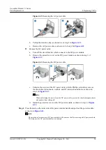
Adjust the retention clip to ensure that it holds the AC power cable tightly.
l
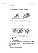
Connect the DC power cables.
a.
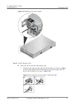
Remove the protective cover on the DC power module, as shown in step 1 of
Figure 4-9
Connecting the DC power cable
b.
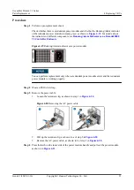
Unfasten the screws of the DC power cable using the Phillips screwdriver, put the
screws through the shock absorption sheets, washers, and OT terminal round holes
in sequence, connect the OT terminal of the black cable to the RTN (+) end, and the
OT terminal of the blue cable to the NEG (-) end, and then fasten the screws, as
shown in step 2 of
.
NOTE
n
When unfastening the screws from the DC power cable, prevent the shock absorption
sheets and washers from sliding off.
n
The colors of DC power cables that connect to the anode and cathode of the DC power
supply are subject to the colors of the DC power cables actually configured in users'
equipment rooms.
c.
Install the protective cover on the DC power module, as shown in step 3 of
.
d.
Turn on the circuit breaker which connects to the DC power module.
Step 11
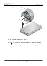
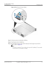
Wait about two minutes and check the status of the Running/Alarm indicator on the power
module to determine whether the power module is successfully installed.
the location of the Running/Alarm indicator.
l
If the indicator is steady green, the power module is successfully installed.
l
If the indicator is blinking green, the power input is normal but the controller enclosure
is powered off.
l
If the indicator is steady red or off, the newly installed power module is faulty or the
power module slot is faulty.
OceanStor Dorado V3 Series
Parts Replacement
4 Replacing CRUs
Issue 05 (2019-01-30)
Copyright © Huawei Technologies Co., Ltd.
17


