ViewPoint 8650
Quick Start Guide
2 Installation Guide
Issue 04 (2013-07-20)
Huawei Proprietary and Confidential
Copyright © Huawei Technologies Co., Ltd.
5
Procedure
Step 1
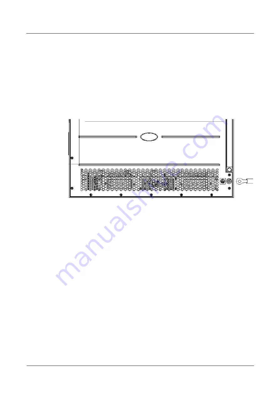
Use a Phillips screwdriver to turn the M6 ground screw anticlockwise to remove it from the
cabinet.
Step 2
Hitch the terminal of the yellowish green ground cable that is provided with the MCU to the
ground screw.
Step 3
Fasten the ground screw to the ground hole securely.
Step 4
Connect the other end of the ground cable to the ground bar on the MCU.
the schematic diagram for connecting the ground cable.
Figure 2-1
Schematic diagram for connecting the ground cable
----End
2.2.2 Connecting the Power Cable
Connecting the DC Power Cable
Connect the DC power cable to the terminal bar as shown in
. Fasten the screws to
secure the connection.
Step 1
Use an M6 sleeve screwdriver to loosen the nut of the terminal of the DC power module.
Step 2
Connect the –48 V OT terminal (the blue one) of the supplied DC power cable to the terminal
(labeled
–48 V
) of the power module. Fasten the nut. Connect the other end of the cable to the
terminal (labeled
–48 V
) of the power supply.
Step 3
Connect the GND OT terminal (the black one) of the supplied DC power cable to the terminal
(labeled
RTN
) of the power module. Fasten the nut. Connect the other end of the cable to the
terminal for providing power input.
Step 4
Connect the PGND OT terminal (the yellowish green one) of the supplied DC power cable to
the terminal (labeled
PGND
) of the power module. Fasten the nut. Connect the other end of
the cable to the grounding board of the MCU.


