background image

ViewPoint 8650 
Quick Start Guide 

2 Installation Guide 


Issue 04 (2013-07-20) 

Huawei Proprietary and Confidential                                     

Copyright © Huawei Technologies Co., Ltd. 


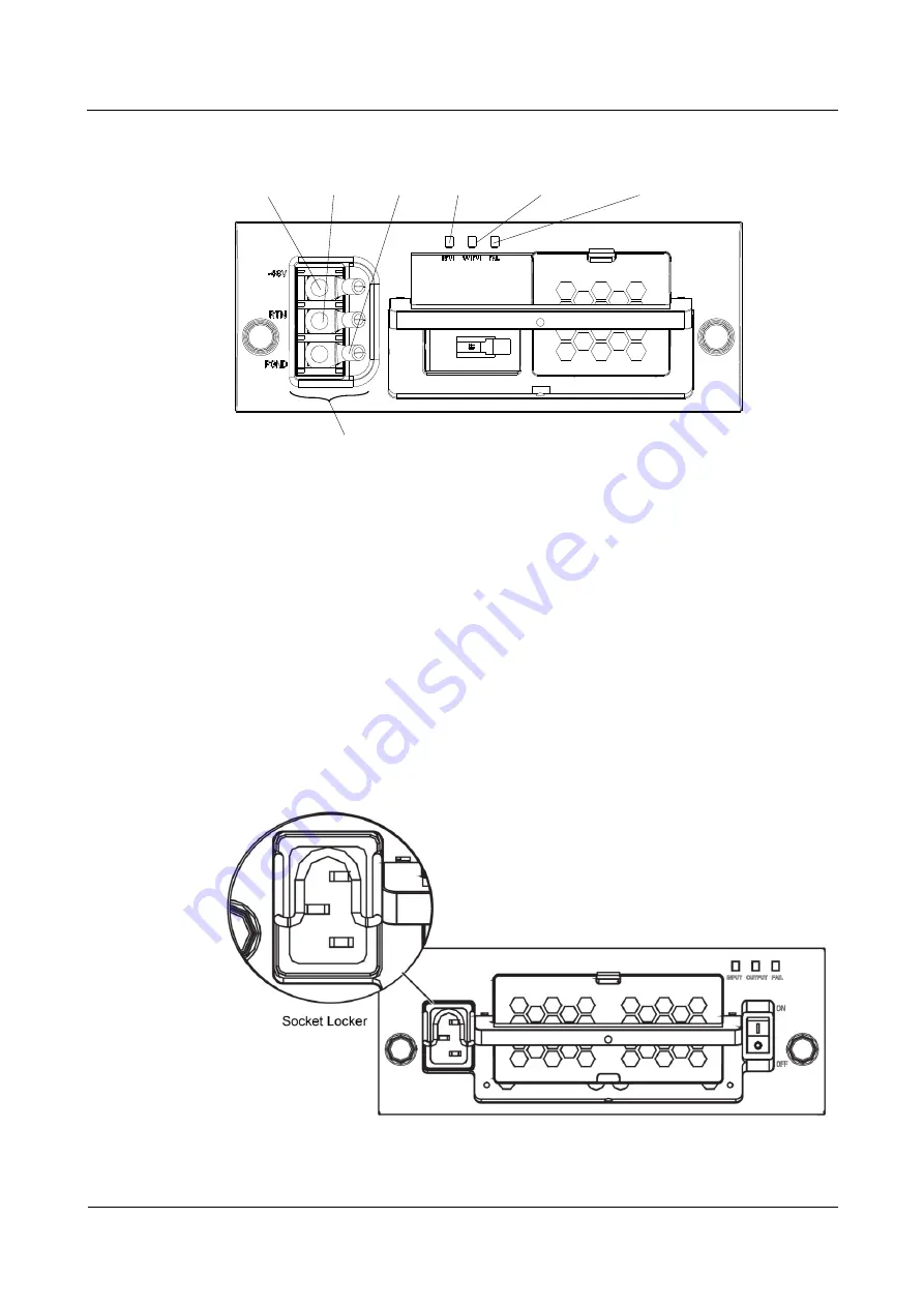
Figure 2-2


Front panel of the DC power module 

-48V

RTN

PGND

Indicator

INPUT

OUTPUT

FAIL

DC terminal bar

Indicator

Indicator


----End 

Connecting the AC Power Cable 

There is a socket locker on the front panel of the AC power module, used to prevent the plug 
from falling off. See

Figure 2-3

. 

Step 1


Pull the socket locker upward. 

Step 2


Insert the plug of the supplied AC power module into the power socket. 

Step 3


Pull the socket locker downward to fix the power plug. 

Step 4


Connect the other end of the power cable into the socket on the wall. 

Figure 2-3


Front panel of the AC power module 


Summary of Contents for ViewPoint 8650 V100R008

Page 1: ...ViewPoint 8650 V100R008 Quick Start Guide Issue 04 Date 2013 07 20 HUAWEI TECHNOLOGIES CO LTD ...

Page 2: ...ei and the customer All or part of the products services and features described in this document may not be within the purchase scope or the usage scope Unless otherwise specified in the contract all statements information and recommendations in this document are provided AS IS without warranties guarantees or representations of any kind either express or implied The information in this document i...

Page 3: ...Network Cable 9 2 2 5 Connecting the Serial Cable 9 3 First Use 10 3 1 Verification Before Power On 10 3 2 Powering On the MCU 11 3 3 Configuring the MCU 12 3 3 1 Logging In to the Web Interface 12 3 3 2 Changing the Password 14 3 3 3 Setting the IP Address 15 3 3 4 Setting the System Time 16 4 Holding a Conference on the Web Interface 18 4 1 Preparing for a Conference 18 4 2 Creating a Conference...

Page 4: ... permitted to make any change to the structure or safety and performance design of the device While using the device observe all applicable laws directives and regulations and respect the legal rights of other people Environment Requirements Place the device in a well ventilated place Do not expose the device to direct sunlight Keep the device clean free of dust and stain Do not place the device n...

Page 5: ...any of the following cases stop using the device immediately disconnect the power supply unplug the power plug smoke sound or smell is emitted from the device Contact the appointed maintenance center for repair Make sure that no object such as metal shavings enters the device through the heat dissipation vent Before connecting any other cable connect the grounding cable of the device Do not discon...

Page 6: ...ed this device The disposal of this device is subject to the Waste from Electrical and Electronic Equipment WEEE directive of the European Union The reason for separating WEEE and batteries from other waste is to minimize the potential environmental impacts and effects on human health of any hazardous substances that may be present EU regulatory conformance Hereby Huawei Technologies Co Ltd declar...

Page 7: ...ere are any anomalies such as incorrect goods missing goods or damaged cartons stop opening the cartons Instead locate the causes and report to the local office of Huawei Technologies Co Ltd 2 2 Installing the MCU and Connecting Cables Before using the MCU place it on a hard flat surface or in a cabinet and then connect cables as required 2 2 1 Connecting the Ground Cable A secure grounding is the...

Page 8: ...the DC Power Cable Connect the DC power cable to the terminal bar as shown in Figure 2 2 Fasten the screws to secure the connection Step 1 Use an M6 sleeve screwdriver to loosen the nut of the terminal of the DC power module Step 2 Connect the 48 V OT terminal the blue one of the supplied DC power cable to the terminal labeled 48 V of the power module Fasten the nut Connect the other end of the ca...

Page 9: ... Indicator End Connecting the AC Power Cable There is a socket locker on the front panel of the AC power module used to prevent the plug from falling off SeeFigure 2 3 Step 1 Pull the socket locker upward Step 2 Insert the plug of the supplied AC power module into the power socket Step 3 Pull the socket locker downward to fix the power plug Step 4 Connect the other end of the power cable into the ...

Page 10: ... resistance value does not meet the requirement use a new antistatic wrist strap An antistatic wrist strap cannot protect the board from the static electricity generated when the board touches your clothes Therefore any contact between the board and clothes should be prevented When you replace the board software or chipset you need to use an antistatic mat When you pick up or plug unplug the chips...

Page 11: ...ectromagnetic shielding effect of the 8650 MCU will be influenced Step 2 Hold the ejector levers outwards in a horizontal manner as shown in picture A in Figure 2 5 Insert the board smoothly along the slot guide rail until the locating pin on the front panel is placed in the pin locating hole on the frame Figure 2 5 Installing the board of the MCU Do not move the board by holding the ejector lever...

Page 12: ...Step 2 Plug the RJ 45 connector at the other end of the network cable to a switch If the video firewall is adopted for networking or if the function of network interface backup is required connect a network cable to the GE1 network interface by using the method for connecting a network cable to the GE0 network interface End 2 2 5 Connecting the Serial Cable Procedure Step 1 Connect the DB9 DB25 co...

Page 13: ...ollowing device installation items All bolts are mounted securely and the device has enough space around for cooling if the 8650 is installed in a cabinet Boards can be inserted and removed smoothly with the fastening screws well tightened The device surface is clean and all parts are in good condition The ESD wrist strap is inserted into the chassis ESD jack All empty slots have filler panels ins...

Page 14: ...e connectors The power and ground cables are 30 mm 1 18 in away from the signal cable outside the cabinet Verifying Power Supply Ensure that the performance of the external AC power supply meets the requirements 3 2 Powering On the MCU Context Do not install both AC and DC power modules in the MCU Procedure Step 1 Use the power cable to connect the AC power module of the MCU to the power socket on...

Page 15: ...ng the MCU 3 3 1 Logging In to the Web Interface Default Settings During your first login to the 8650 web interface use the default settings listed in Table 3 1 Table 3 1 Default settings Parameter Value IP address of the GCCA board GE0 port 192 168 2 1 User name of the web interface administrator admin Password of the web interface administrator ViewPoint 8660 V100R008C01B017SP03 or an earlier ve...

Page 16: ...r connect the client computer and to 8650 to the same switch in the LAN Step 2 In the address bar of the browser enter the IP address of the GE0 network interface of 8650 The default IP address is 192 168 2 1 Press Enter The login page of the Web interface is displayed as shown in Figure 3 3 Figure 3 3 Login page of the Web interface If you are unable to access the MCU web interface using HTTP use...

Page 17: ...ure 3 4 it indicates that you have logged in to the Web interface successfully Figure 3 4 Home page of the Web interface To improve system security change the password at your first login End 3 3 2 Changing the Password You can change your password after logging in to the Web interface of the MCU Procedure Step 1 Choose Users Change password to display the Change Password page as shown in Figure 3...

Page 18: ...s Before changing IP address of the GCCA board GE0 port contact your network administrator to obtain the actual IP settings for the items listed in Table 3 2 Table 3 2 IP settings Parameter Default Value Actual Settings IP address 192 168 2 1 Example 200 54 0 120 Subnet mask 255 255 0 0 Example 255 255 0 0 Gateway address 192 168 2 254 Example 200 54 0 1 Procedure Step 1 Log in to the 8650 web int...

Page 19: ... in Table 3 2 Retain the default settings for other parameters Step 6 Click OK Step 7 Repeat Step 2 through Step 6 to set the IP parameters for GE0 ports in other boards The IP address of the GE0 port on the GCCA board is used to log in to the 8650 web interface Keep record of this IP address End 3 3 4 Setting the System Time To start conferences at the correct time set the 8650 system time to the...

Page 20: ...Technologies Co Ltd 17 The System page is displayed Step 3 Choose Time The Time page is displayed as shown in Figure 3 7 Figure 3 7 Time page Step 4 Edit Date and Time based on the actual time If the client computer s local time is correct click Obtain Operating System Timeto correct the system time Step 5 Click OK End ...

Page 21: ... Then you can hold a simple conference 4 1 Preparing for a Conference The 8650 web interface supports conference management functions You can initiate a conference by simply connecting endpoints to the 8650 Planning Data This section describes how to plan data to initiate a conference attended by two participants on the 8650 web interface Table 4 1 lists the conference data plan Table 4 1 Conferen...

Page 22: ...unctions as a bridge to transfer call information between videoconferencing endpoints and the MCU translates the addresses of the videoconferencing endpoints and the MCU and controls calls and bandwidth The 8650 supports Built In GK you can set the Built In GK enabled and registers 8650 with it Step 1 Enable Built In GK 1 Log in to the MCU web interface 2 Choose Gatekeeper Settings 3 Select Enable...

Page 23: ...d The MCU does not register with a GK When scheduling a conference the MCU can call participants only using their IP addresses GK address IP address of the GK If the embedded GK is enabled you do not need to set this parameter If the embedded GK is disabled enter the IP address of an online standalone GK GK ID ID of the GK on the MCU web interface Example GK1 MCU alias Alias used by the MCU to reg...

Page 24: ...reated you can create a conference Then you can choose to initiate the conference immediately or save the conference as a conference profile 4 2 1 Setting GK Registration Parameters on a Videoconferencing Endpoint To initiate a conference all participant endpoints must register with a GK This section describes how to register an endpoint with a GK using the HUAWEI ViewPoint 9000 HD videoconferenci...

Page 25: ...stem Settings Protocol H 323 SIP Settings The page that contains the H 323 area is displayed as shown in Figure 4 4 Figure 4 4 H 323 parameters Step 3 Set the parameters listed in Table 4 4 Table 4 4 H 323 parameters Parameter Description Setting Enable GK Whether the endpoint registers with the GK Enable The endpoint registers with the GK after being started The GK functions as a bridge to transf...

Page 26: ...this parameter to the IP address of the SC server Example 200 54 0 144 E 164 Participant number for the endpoint After the endpoint registers with a GK this number can be used to call the endpoint The number contains a maximum of 32 digits Example 0100001 H 323 ID Name by which a GK identifies the endpoint after it registers with the GK The name can consist of digits letters and special characters...

Page 27: ...add at least two participant endpoints that has registered with a GK Prerequisites The participant endpoints to be added have registered with a GK For details see 4 2 1 Setting GK Registration Parameters on a Videoconferencing Endpoint Procedure Step 1 Log in to the 8650 web interface Step 2 Choose Phone Book Participants The Participants page is displayed Step 3 Click Add IP Participant The Add I...

Page 28: ... 4 Set the participant parameters listed in Table 4 5 Table 4 5 Participant parameters Parameter Description Setting Participant name Name used to identify a participant The name must meet the following requirements Contain 1 to 64 characters Cannot end or start with a space Example site1 Type Type of a participant Terminal participant that uses an HD or SD videoconferencing endpoint Upper level M...

Page 29: ...dpoint NOTE If a GK is enabled for a conference enter the value of E 164 which is predefined when 4 2 1 Setting GK Registration Parameters on a Videoconferencing Endpoint Example 0100001 Participant Password Password used for the authentication performed when a participant endpoint registers with a GK This password must be the same as the password defined on the participant endpoint Set this param...

Page 30: ...nt Succeed Step 6 Repeat Step 3 through Step 5 to add another participant endpoint End 4 3 Scheduling a Conference Prerequisites Before scheduling a conference ensure that All participant endpoints have registered with the 8650 embedded GK The conference involves two participant endpoints or more Set the connection mode to Built in web Procedure Step 1 Log in to the 8650 web interface Step 2 Choos...

Page 31: ...n Table 4 6 Table 4 6 General conference parameters Parameter Description Setting Conference Name Name of the conference you want to schedule Enter a string of 1 to 64 characters Example Conference 1 Default Duration Duration of the conference Value range 10 360 Unit minute Default value 120 Quality It specifies the audio visual parameters and transmission rate of the conference The higher the lev...

Page 32: ...er Number used by participants to join a conference If you set Conference Type to Common the MCU will assign an Access Number to the conference automatically when scheduling the conference Preset Banner Captio n When enabling the Banner or Caption it functions as an explanation for a conference For details of other general conference parameters click Step 4 Click Next The Select Participants dialo...

Page 33: ...e Book Step 6 Select participants from the participant list and click Add Step 7 Click Close Step 8 Click Save and schedule a conference The Schedule dialog box is displayed as shown in Figure 4 10 Figure 4 10 Schedule dialog box Step 9 Set Start date and Start time Step 10 Click Schedule The The conference has been scheduled message is displayed in the lower right corner of the page End ...

Page 34: ...rticipant This is used to call a selected participant to enable the participant to join the conference Hanging up participant This is used to disconnect a selected participant Unmute Speaker This is used to unmute the speaker of a selected participant so that the participant can hear the other participants of the conference Mute Speaker This is used to mute the speaker of a selected participant so...

Page 35: ...articipant is broadcast In this case the microphones of all the participants except the chair participant and the broadcasting participant are muted Voice Activation This is used to adjust the sensitivity of voice activation If the voice activation function is enabled during a conference the MCU automatically switches the broadcasting participant to the participant with the loudest voice Cancel Ch...

Page 36: ... in In this case the participant needs to call the MCU to join the conference Single dial out This is used to set the call mode of a participant to Single dial out In this case the MCU needs to call the participant to add the participant to the conference Start Multicast This is used to enable the multicast function The multicast parameters are set in the corresponding conference profile End Multi...

Reviews: