22
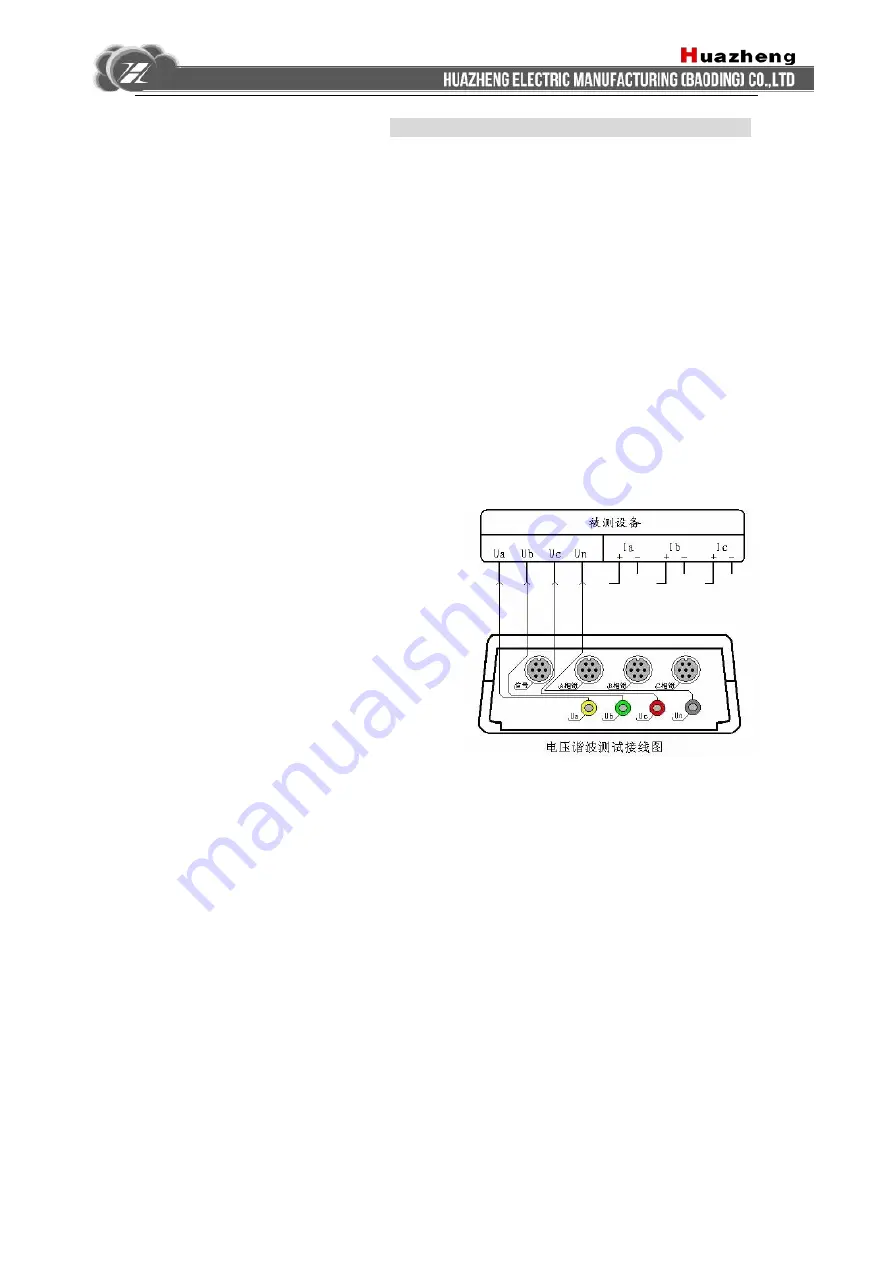
Perform wiring in accordance with wiring diagram for testing three-phase three-wire devices
if the device is a three-Phase three-wire connection mode one.
Go to the "Spectrum Analysis Interface" for testing after wiring.
(V) Analysis of voltage harmonic section
1 Purpose for testing
This function is used to display the numerical and percentage content of 2-64 harmonic
content of the three-phase voltage parameters, in order to determine whether power quality of the
measured voltage signal is good or bad.
2 Testing method
(
被测设备:
tested equipment
信号:
signal
A
相钳:
phase-A clamp
B
相钳:
phase-B clamp
C
相钳:
phase-C
clamp
电压谐波测试接线图:
Voltage Harmonics Test
Wiring Diagram)
Specific wiring as shown at right:
In this project, three-phase voltage signal is simultaneously accessed. Make sure that four colors
of yellow, green, red, black, the voltage test lines are respectively corresponding to A, B, C, N
four-phase lines of measured signals (connect phase-B voltage of the test equipment to Un
terminal of the instrument when PT secondary is three-wire, with only three voltage lines
available). Go to the "Voltage Harmonics" interface for checking test results after wiring.
(VI) Analysis of current harmonic section
1 Purpose for testing
This function is used to display the numerical and percentage content of 2-64 harmonic


