23
content of the three-phase current parameters, in order to determine whether power quality of the
measured current signal is good or bad.
2 Testing method
(
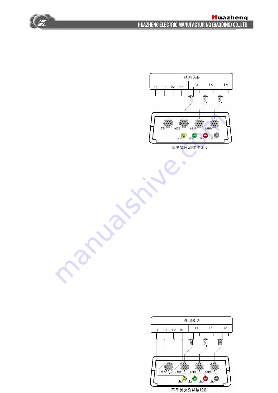
被测设备:
tested equipment
信号:
signal
A
相钳:
phase-A clamp
B
相钳:
phase-B
clamp
C
相钳:
phase-C clamp
电流谐波测试接线图:
Current Harmonics Test
Wiring Diagram)
Specific wiring as shown at right:
In this project, three-phase current signal is simultaneously accessed. Measure A, B, C three-phase
current loop of the device under test using A, B, C three clamp current transformers
respectively( Only use A, C two-phase clamps when the device under test is in three-phase
three-wire connection mode). Go to the "Current Harmonics" interface for checking test results
after wiring.
(VII) Unbalance measurement section
1 Purpose for testing
This function is used to display voltage amplitude of sub-phase, three times the
zero-sequence voltage 3U0, zero-sequence voltage U0, positive sequence voltage U1, negative
sequence voltage U2, voltage unbalance value #u; each sub-phase current amplitude and 3 times
the zero sequence current 3I0, zero-sequence current I0, positive sequence current I1, negative
sequence current I2, and current unbalance value #i. So you can assess the impact of voltage and
current unbalance to power quality.
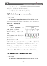
2 Testing method
Specific wiring as shown at right: (
被测


