14
Huba Control AG |
Industriestrasse 17, 5436 Würenlos - 699M - Edition 02/2020 -
120225
Technische Änderungen vorbehalten | Technical data subject to change | Sous réserve de modifications techniques
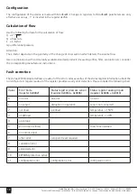
Configuration
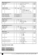
The configuration of the device is made with Modbus®. Changes in registers for Modbus® parameters are only
effective as soon as
„1“
is inserted in the register 4x768.
Calculation of flow
Use the following formula for the calculation of flow:
Q = k * √∆
Δ
p
Q = flow rate
k = k-factor
Δ
p = differential pressure
Attention:
The k-factor depends on the geometry of the change of cross section which detects the volume flow
Use in combination with commercially available standard products (measuring orifice, filter, ventilation etc.) consider
the corresponding manufacturer instructions.
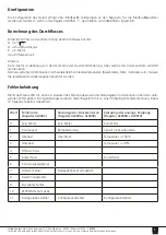
Fault correction
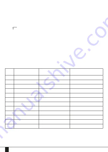
The status-LED blinking red allows a readout of the error codes as well as of the status register information about the
current failure. A regular readout of the register provides a early error detection. Please consider the following chart.
Value
Error Code
(register 4x0002)
Status register pressure sensor
(register 4x0006)
Status register analog inputs
(register 4x0010)
0
no error
no error
no error
1
no sensor
disruption in operation
sensor not connected
2
overload
overload
temperature > 150ºC
3
underload
temperature < -40ºC
4
open loop
5
short time overload
short time overload
6
no output signal
7
other error
zero point reset required
8
calculation error
9
extended error
10
EEPROM protection active
11
configuration error
configuration error
configuration error

