background image

9

Huba Control AG | 

Industriestrasse 17, 5436 Würenlos - 699M - Edition 02/2020 - 

120225

Technische Änderungen vorbehalten | Technical data subject to change | Sous réserve de modifications techniques  

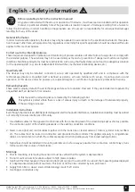
Before operating refer to the instruction manual!

Any person entrusted with the set-up or operation of the device, must have read and understood this operation 
manual, in particular all safety notes.The guarantee is invalid in respect of damage resulting from a failure to 

follow the instructions, incorrect handling or inappropriate use. We accept no responsibility for consequential damages 
resulting from any of the above.

General information

In order to ensure safe operation, the device may only be operated in accordance to the specifications stated in this opera-
tion manual. Futhermore, all legal and safety regulations concerning this specific application should be observed.This also 
applies to the use of accessories.

Correct use to the intended purpose

These devices are designed for indication and monitoring of process variables. All other forms of usage do not comply with 
the intended purpose. These sensors may not be used solely as means for prevention of dangerous machine and system 
conditions. Machines and systems must be constructed in such a way, that faulty states cannot lead to a dangerous situation 
for the operating staff (e.g. due to independent limit switches, mechanical interlocking devices, etc.).

Qualified staff

The devices may only be installed, connected, set-up and operated by qualified staff and in compliance with the 
technical specifications. Qualified staff is defined as persons, who are familiar with set-up, mounting, start-up and 
operation of this device and who possess a recognized degree or certificate of appropriate professional training.

Remaining hazards

These sensors employ state-of-the-art technology and are safe to operate. However, if they are installed and operated by 
unqualified staff, an element of risk remains. 

In this manual the remaining risks are marked by the following symbol:
This symbol is posted where there is a risk of serious injury or death or the damage of material and property, 
if the warning is ignored

Installation instructions

Even though the device is excellently protected against electro-magnetic interference, installation and cabling must be carried 
out correctly to ensure interference immunity.

1.  Use shielded cables for the signal and control lines with the connecting lead of the screen being kept as short as possible. 


  The connection point of the shielding depends on the existing connection conditions.

2.  Never route signal and control cables together with the trunk line or feeder cables of motors, cylinder coils, rectifiers  
  etc. The cables must be routed in conductive and grounded cable conduits. This applies especially to long-distance  
  cables, or environments in which the cables are exposed to strong radio waves from broad casting stations.

3.  Signal lines should be installed in mounting cabinets and as far away as possible from contactors, control relays, trans 
  formers and other sources of interference.

Montage

•   Prior to mounting or removing the sensor it must be verified that the system is depressurized.
•   Do not mount sensors in locations subject to high pressure pulses.
•   Significant thermal changes in the sensor environment can lead to a zero shift. As a result, the measuring value displayed 


  in a depressurized state will not read zero. This kind of drift can be corrected by zero point reset.

•  Supply from SELV or class 2 source limited energy circuit 15 W or less
•  Use Copper conductors only

English - Safety information 

Summary of Contents for 699M

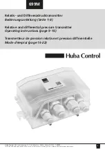
Page 1: ...Technical data subject to change Sous r serve de modifications techniques 699M Relativ und Differenzdrucktransmitter Bedienungsanleitung Seite 1 8 Relative and differential pressure transmitter Operat...

Page 2: ...verf gen Restgefahren Die Sensoren entsprechen dem Stand der Technik und sind betriebssicher Von den Ger ten k nnen Restgefahren ausgehen wenn sie von ungeschultem Personal unsachgem eingesetzt und b...

Page 3: ...cktransmitter Vertikal Druckanschl sse nach unten Abfluss von eventuellem Kondenswasser in den Druckleitungen Werkeichung Soll nur eine Relativmessung erfolgen so wird der Druckanschluss mit der Bezei...

Page 4: ...ung Modbus Terminierung 1 Ein 120 1nF 0 Aus Taster Bet tigungsdauer Funktion 5 10 s Nullpunkt Reset 10 20 s Auf Werkseinstellungen zur cksetzen Nullpunkt Reset Mittels Nullpunkt Reset k nnen Druckabwe...

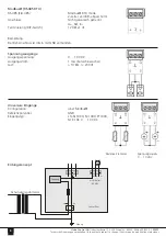
Page 5: ...g 1 GND Analogeingang 2 Spannungsversorgung Betriebsspannung 24V AC DC 15 Betriebsfrequenz 45 65Hz Stromverbrauch 2 VA Ausgangsstrom f r externe Sensoren 80 mA Ausgang ist intern abgesichert Bemerkung...

Page 6: ...vanisch getrennt A Ref B Terminierung DIP Switch 120 1 nF Bemerkung Der Ref Anschluss ist intern mit GND verbunden Spannungsausg nge Ausgangsspannung 0 10 VDC Ausgangsstrom 1 mA Kurzschlusssicher Last...

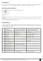
Page 7: ...rdprodukten Messblende Filter Ventilation etc m ssen die jeweiligen Herstellerangaben beachtet werden Fehlerbehebung Blinkt das Status LED rot kann ein Auslesen des Fehlercodes sowie der Statusregiste...

Page 8: ...rmaler Betriebsmodus Gr n flackernd Buskommunikation Blau kontinuierlich Nullpunkt zur cksetzen Elektromagnetische Vertr glichkeit Dieses Produkt entspricht den Anforderungen der EMV Richtlinie 2014 3...

Page 9: ...ecognized degree or certificate of appropriate professional training Remaining hazards These sensors employ state of the art technology and are safe to operate However if they are installed and operat...

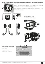
Page 10: ...sure transmitter Vertical with pressure connections facing downwards drain of possible condensed water factory calibration For the measurement of relative pressure the indication connected to ambient...

Page 11: ...ressing Modbus termination 1 On 120 1nF 0 Off Push Button Duration of operation Function 5 10 s Zero point reset 10 20 s Reset to factory setting Zero point reset Reset pressure variations with the ze...

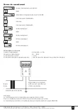
Page 12: ...ND analogue output 2 analogue input 1 GND analogue input 2 Voltage supply Operating voltage 24V AC DC 15 Operating frequency 45 65Hz Power consumption 2 VA Output for external sensors 80 mA Output is...

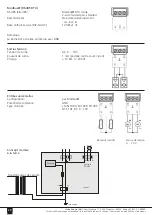
Page 13: ...alvanically separated A Ref B Termination DIP Switch 120 1nF Comment The reference connection is internally connected to GND Voltage output Output voltage 0 10 VDC Output current 1 mA Short circuit pr...

Page 14: ...rifice filter ventilation etc consider the corresponding manufacturer instructions Fault correction The status LED blinking red allows a readout of the error codes as well as of the status register in...

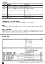
Page 15: ...e Green continuous start up Green blinking normal operating mode Green flickering bus communication Blue continuous zero point reset Electromagnetic compatibility This product complies with the EMC re...

Page 16: ...ers Les transmetteurs correspondent au niveau technologique d aujourd hui et poss dent un fonctionnement s r Les appareils peuvent n anmoins pr senter un danger r siduel en cas de montage ou d utilisa...

Page 17: ...on diff rentielle Verticale embouts de pression vers le bas s assurer de l vacuation de l eau de condensation ventuelle dans les flexibles talonnage usine Si une mesure de pression relative est r alis...

Page 18: ...du Modbus 0 Hors 120 1nF 1 EN Bouton poussoir Dur e d appui Fonction 5 10 s Remise z ro mesure 10 20 s Retour param tres usine Remise z ro mesure La remise z ro mesure permet de mettre z ro un d calag...

Page 19: ...analogique 2 Alimentation en tension Tension d alimentation 24V AC DC 15 Fr quence d alimentation 45 65Hz Consommation courant 2 VA Courant de sortie pour appareils externes 80 mA la sortie dispose d...

Page 20: ...ef B Mise en hors service DIP Switch 120 1 nF Remarque La borne Ref est reli e en interne avec GND Sorties tension Tension de sortie DC 0 10V Courant de sortie 1 mA prot g contre court circuit Charge...

Page 21: ...ltre ventilateur etc les indications des constructeurs doivent tre utilis s D pannage Lorsque la LED d tat rouge clignote le code d erreur peut tre lu dans le registre d tat La lecture anticip e de ce...

Page 22: ...e de s curit peut tre d sactiv dans le registre 4x0015 Register table Addr Description Unit Scaling R W Range Data Type 4x0001 Type 1 R 9710 1 x 1250Pa 9720 1 x 2500Pa 9750 1 x 5500Pa 9770 1 x 7000Pa...

Page 23: ...Pa Pa 1 R uint16_t 4x0039 Value PSI PSI 0 0001 R uint16_t 4x0040 Zero point calibration 1 R W 0 no action 1 zero point calibration P1 P2 2 zero point calibration P2 3 zero point reset to factory setti...

Page 24: ...6_t 4x0075 Average 16000 ms R uint16_t 4x0081 Flow low 0 01 R uint16_t 4x0082 Flow high 0 01 R uint16_t 4x0083 k factor 1 R W 0 VAL 1500 uint16_t 4x0084 Unit 1 R W 0 m3 h default 1 m3 s 2 l s uint16_t...

Reviews: