INSTALLATION
Testing
Troubleshooting
Operation
Maintenance
1. Remove the front cover. When required, remove battery to access J-Box mounting holes.
2. Mount the equipment securely in place on the wall. Two additional 'Key Hole' mounting holes are located at the top of the unit
housing in addition to the 'J-Box' mounting holes. These '2' additional mounting slot holes must be used when the unit is mounted
to the wall. Additional chain support may be required by local codes. Chain hook holes are provided at each end of the enclosure.
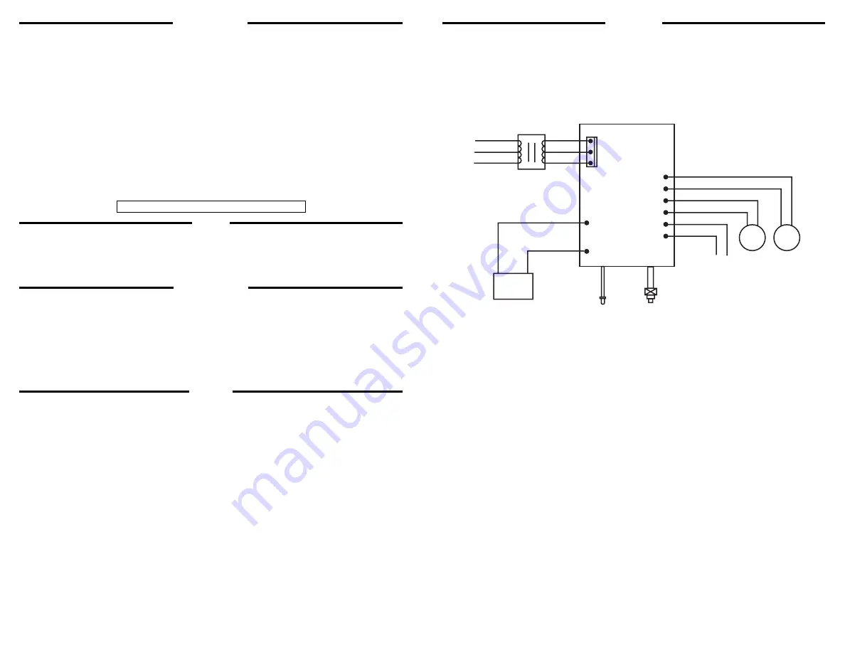
3. Extend 24 hr AC supply of rated voltage to the equipment, which is furnished with a dual voltage (120/277V) field selectable
input. Connect unit to utility power using an approved connector. For 120V supply connect the line wire to the black lead and for
277V supply connect the line wire to the red lead. Connect neutral wire to the white lead. The ground wire (green lead) needs to
be connected in accordance with the local codes. DO NOT energize the circuit at this time. (CAUTION: Insulate the unused black
or red wire. Failure to do so may cause an unsafe condition.)
4. If remote fixtures are to be connected to the equipment extend the remote circuit in accordance with Article 700 and 720 of the
National Electric Code (NEC) and connect to the yellow and violet leads coming out of the unit. (CAUTION: The minimum wire
size required by the NEC is 12 gauge Copper or equivalent. Your installation may require larger sized wire to ensure that the
voltage drop DOES NOT exceed 5%. Do not exceed the total output rating of the equipment including any additional mounted
heads.)
5. Install and connect the battery. Refer to the Illustration. Connect the Red (+) lead from the PC board assembly to the positive (+)
terminal on the battery and the Blue (-) lead from the PC board assembly to the negative (-) terminal. (CAUTION: Observe polar-
ity. Failure to connect the battery properly will result in equipment failure and an unsafe condition.) NOTE: The Emergency lights
will NOT come ON at this time.
6. Energize the unit with AC supply. The charge indicator will illuminate.
7. Replace the unit cover.
8. Adjust and focus the lighting heads as required.
1. Apply AC power to the unit. The LED indicator should turn RED.
2. After the battery has been left to charge for 2 hours, test the unit by pushing the switch. The LED indicator turns OFF and the
lamps on the unit turn ON
3. When the switch is released, the lamps turn OFF and the LED indicator turns back to RED.
National Electric Code (NEC) and NFPA life safety code regulations require that routine tests need to be performed as listed below;
Once every month, the unit needs to be tested for duration of 30 seconds. Push in and hold the test switch to perform this test.
Once every 12 months, a full 90 minute (per UL requirements) test needs to be performed on the unit. Disconnect power to the unit and
leave it in emergency mode. The lamps should stay ON for at least 90 minutes.
Condition - The emergency lights do not operate
1. If the charge indicator light is off: Check that the circuit breaker for AC supply is ON.
2. If the charge indicator light is ON: Check that the battery is properly connected. If problem persists, Replace battery.
If remote lamps are connected to the equipment, then turn OFF the AC supply and disconnect the remote circuit wires from the
equipment itself) come ON, then check the remote circuit for short or overload condition and correct as required. Reconnect the
circuit wires and restore the AC power.
Caution: IAlways turn off AC power to the equipment before servicing. Servicing should be performed only by a qualified service
technician. Use only MANUFACTURER supplied replacement parts.
1.
BATTERY: The battery supplied in this equipment requires no maintenance. However, it should be tested periodically (see
TESTING) and replaced when it no longer operates the connected fixtures for the duratiion of a 30-second or 90-minute test.
The battery supplied in thsi equipment has a life expectancy of 5-7 years when used in a normal ambient temperature 72°F.
2.
OTHER: Clean lenses and replace lamps, as and when required.
If the local lamps don’t turn ON after disconnecting the remote circuit wires, then replace battery.
Condition - Emergency lights are dim
1.
Battery not fully charged. Allow battery to recharge for 24 hours and then retest. If lights are still dim, replace battery.
BATTERY
BLUE(-)
BLAC K
ORANGE
277 VA C
120 VA C
NEUTRAL
BLAC K
WHIT E
TRANSFORMER
PCB BOARD
RED
)
)
)
BLUE(-)
BLUE(-)
+
_
To Remot e LAMP
LAMP
LAMP
AC ON
TEST
Chicago LED DXR
Note: The Maximum mounting height for this model is 19 feet.