
Manual M-800 Rev. 6/09
Manual M-800 Rev. 6/09
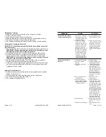
Pump Operation
When operating the pump for the first time:
1. All valve and hose connections should be secure, and the reservoir should be
filled to the proper level. Connect the power supply.
2. Activate the pump, and advance the cylinder(s) by pushing the UP button
on the remote control switch. The motor shuts off when the UP button is
released, and system pressure is held. Press the DOWN button or shift the
manual valve to allow the cylinder(s) to retract.
3. Refer to the section titled “Bleeding Air from the System.”
4. Check the oil level in the reservoir and add oil if necessary. The reservoir oil
level should be within 1” of the pump cover plate.
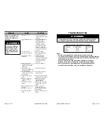
PRESSURE REGULATING CONTROL ADJUSTMENTS
(NOTE: These options are not on all pump models.)
Adjusting the Pressure Regulating Valve
The pressure regulating valve can be adjusted to bypass oil at a given pressure
while the pump continues to run.
IMPORTANT:
• For easy adjustment of the pressure regulating valve, always adjust the
pressure by
increasing
it to a desired pressure setting. The pressure
range for this unit is from 1,000 PSI to 10,000 PSI.
1. Loosen the locknut on the pressure regulating valve, and turn the adjusting
screw a few turns counterclockwise (CCW) to decrease the pressure setting
to a lower than desired pressure.
2. Connect the pump completely. Place the motor control switch in the Run
position and push the Start button.
3. Slowly turn the adjusting screw in a clockwise (CW) direction to gradually
increase the pressure setting. When the desired pressure setting is reached,
lock the adjusting screw into position by tightening the locknut.
Page 4 of 16
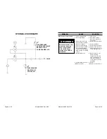
OPERATING INSTRUCTIONS
Hydraulic Connections
1. Clean all the areas around the oil ports of the pump and cylinder(s).
2. Inspect all threads and fittings for signs of wear or damage, and replace as
needed.
3. Clean all hose ends, couplers, or union ends.
4. Remove the thread protectors from the hydraulic oil outlets.
5. Connect the hose assembly to the hydraulic oil outlets, and couple the hose to
the cylinder.
IMPORTANT: Seal all external pipe connections with a high-quality,
non-hardening thread sealant. Teflon tape can be used to seal hydraulic
connections if only one layer of tape is used. Apply the tape carefully,
two breads back, to prevent it from being pinched by the coupler and
broken off inside the system. Any loose pieces of tape could travel
through the system and obstruct the flow of oil or cause jamming of
precision-fit parts.
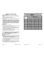
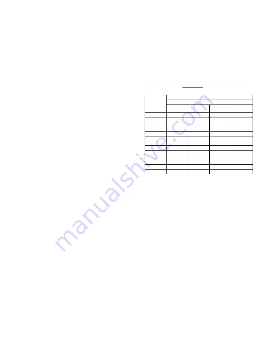
RECOMMENDED MINIMUM WIRE SIZE-AWG (mm
2
)
OF EXTENSION CORDS FOR ELECTRIC PUMPS
Current
At Full Load
(Amps)
Cord Size AWG (mm2) 3.2 Volt Drop
Length of Cord
0-25 feet
(0-8 m)
25-50 feet
(8-15 m)
50-100 feet
(15-30 m)
100-150 feet
(30-45 m)
6
18 (.82)
16 (1.33)
14 (2.09)
12 (3.32)
8
18 (.82)
16 (1.33)
12 (3.32)
10 (5.37)
10
18 (.82)
14 (2.09)
12 (3.32)
10 (5.37)
12
16 (1.33)
14 (2.09)
10 (5.37)
8 (8.37)
14
16 (1.33)
12 (3.32)
10 (5.37)
8 (8.37)
16
16 (1.33)
12 (3.32)
10 (5.37)
8 (8.37)
18
14 (2.09)
12 (3.32)
8 (8.37)
8 (8.37)
20
14 (2.09)
12 (3.32)
8 (8.37)
6 (13.30)
22
14 (2.09)
10 (5.37)
8 (8.37)
6 (13.30)
24
14 (2.09)
10 (5.37)
8 (8.37)
6 (13.30)
26
12 (3.32)
10 (5.37)
8 (8.37)
6 (13.30)
28
12 (3.32)
10 (5.37)
6 (13.30)
4 (21.29)
30
12 (3.32)
10 (5.37)
6 (13.30)
4 (21.29)
Page 13 of 16


