
Manual M-800 Rev. 6/09
Manual M-800 Rev. 6/09
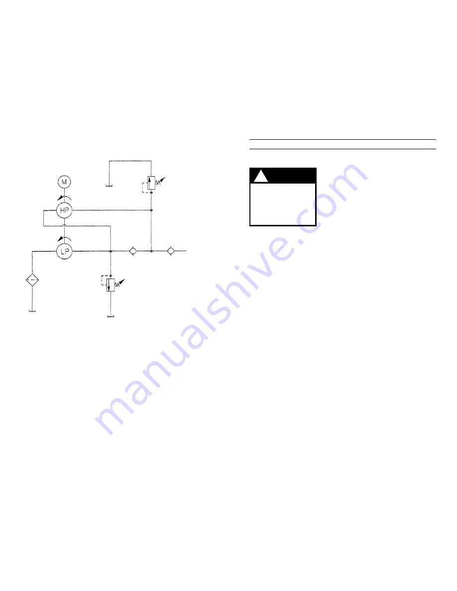
HYDRAULIC SCHEMATIC
MAX. PRESSURE
SAFETY RELIEF VALVE
REFER TO YOUR
PUMP’S NAMEPLATE
SUPERCHARGE
RELIEF VALVE
260 / 280 PSI
TO VALVE
Page 8 of 16
PROBLEM
CAUSE
SOLUTION
Electric motor does not run.
1. Unit is not plugged in.
2. No voltage supply.
3. Broken lead wire or de-
fective power cord plug.
4. Defective switches.
5. Defective started relay.
6. Defective remote switch.
7. Circuit breaker tripped
because total amperage
draw too high for existing
circuit.
8. Overheated motor.
9. Faulty thermal protector.
10. Defective motor
1. Plug in unit.
2. Check line voltage.
Check reset button on
power panel.
3. Replace defective parts.
4. Replace switches.
5. Replace defective parts.
6. Replace remote switch.
7. Add an additional circuit
or use alternate circuit.
8. Wait for motor to cool
before restarting.
Thermal protector will
reset automatically, or
push red reset button
on tip of the motor (if so
equipped).
9. Replace.
10. Replace or repair motor.
Disconnect power sup-
ply before removing
cover. Any electrical
work should be per-
formed by a qualified
electrician.
WARNING
!
Page 9 of 16


