background image

Pub. 42004-561A 


G A I - T R O N I C S

®


A   H U B B E L L   C O M P A N Y  

400-005 and 400-006 RigCom Stations


T

A B L E   O F  

C

O N T E N T S


GAI-TRONICS  3030 KUTZTOWN RD. READING, PA  19605 USA 

610-777-1374  

  800-492-1212  

  Fax:  610-796-5954 

V

ISIT WWW

.

GAI

-

TRONICS

.

COM FOR PRODUCT LITERATURE AND MANUALS


Confidentiality Notice .....................................................................................................................1


General Information .......................................................................................................................1


Important Safety Instructions .........................................................................................................2


Installation ......................................................................................................................................2


Speaker Horn Assembly ......................................................................................................................... 3


Mounting .................................................................................................................................................. 3


Hardware Configuration ........................................................................................................................ 3


Internal .................................................................................................................................................. 3 
External ................................................................................................................................................. 3 

Wiring ...................................................................................................................................................... 5


System Wiring ...................................................................................................................................... 5 
Station Wiring ....................................................................................................................................... 5 
System Line Balance ............................................................................................................................. 6 
Field Connections ................................................................................................................................. 8 

Cover Installation .................................................................................................................................. 10


Operation .......................................................................................................................................10


Common Line System ........................................................................................................................... 11


Master/Slave System ............................................................................................................................. 11


Maintenance ..................................................................................................................................12


F1/F2 Fuses ............................................................................................................................................ 12


Troubleshooting .................................................................................................................................... 12


Replacement Parts and Accessories .................................................................................................... 13


Specifications ................................................................................................................................13


AC Power ............................................................................................................................................... 13


DC Power ............................................................................................................................................... 13


Amplifier PCBA .................................................................................................................................... 13


Speaker (Model 400-005 Only) ............................................................................................................ 13


Mechanical ............................................................................................................................................. 14


Environmental ....................................................................................................................................... 14


Approvals .......................................................................................................................................14


Appendix A—Interfacing a Model 400-005 RigCom Station to EZ Page Stations ......................................14


Summary of Contents for GAI-TRONICS 400-005

Page 1: ...tions 2 Installation 2 Speaker Horn Assembly 3 Mounting 3 Hardware Configuration 3 Internal 3 External 3 Wiring 5 System Wiring 5 Station Wiring 5 System Line Balance 6 Field Connections 8 Cover Installation 10 Operation 10 Common Line System 11 Master Slave System 11 Maintenance 12 F1 F2 Fuses 12 Troubleshooting 12 Replacement Parts and Accessories 13 Specifications 13 AC Power 13 DC Power 13 Amp...

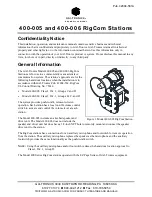
Page 2: ...azardous locations when the installation is in accordance with GAI Tronics Pub 42004 562 RigCom UL Control Drawing No 75614 Model 400 005 Class I Div 1 Groups C and D Model 400 006 Class I Div 1 Groups B C and D The system provides push to talk release to listen operation Each station has a local on off volume control switch to activate and control the volume level at each station The Model 400 00...

Page 3: ... product manufacturer as they may cause hazards This permanently connected apparatus must have an ALL POLE MAINS switch with a contact separation of at least 3 mm in each pole incorporated in the electrical installation of the building WARNING To reduce the risk of fire or electrical shock do not expose this apparatus to rain or moisture Installation Only trained qualified and competent personnel ...

Page 4: ...the driver bushing 4 Position two large diameter fiber washers with the large diameter steel washer sandwiched between them on the speaker bushing 5 Place the small diameter rubber washer into the speaker horn tip followed by the small diameter fiber washer 6 Screw the speaker horn tip to the driver bushing until it is snug Mounting NOTE The mounting surface must be able to support the weight of t...

Page 5: ...V I GROUPS C D WARNING EXPLOSION HAZARD DO NOT DISCONNECT EQUIPMENT UNLESS TO REDUCE THE RISK OF IGNITION OF HAZARDOUS ATMOSPHERES CONDUIT SEALS MUST BE INSTALLED WITHIN 18 INCHES OF ENCLOSURE AMBIENT TEMPERATURE 20 C TO 60 C No 400 005 RIGCOM INTEGRAL SPEAKER DATE CODE 13R2 WARNING 120VAC 50 60 Hz 0 4 AMP MAX OR KEEP COVER TIGHT WHILE CIRCUITS ARE ALIVE CAUTION POWER HAS BEEN SWITCHED OFF OR THE ...

Page 6: ...istance Figure 4 Number of Stations vs Line Length StationWiring 1 Attach conduit or cable glands to the inch NPT holes on the bottom of the enclosure 2 Feed the low voltage wiring through the conduit or cable gland and into the left side hole as viewed from the front of the station 3 Feed the power wiring through the conduit or cable gland and into the right side hole as viewed from the front of ...

Page 7: ...eet using No 18 AWG wire 7 If using the 51052 003 Auxiliary Footswitch Assembly Connect the assembly to the station at terminal block TB4 8 and TB4 9 and the shield to TB4 5 if used The maximum distance from the station is 50 feet using No 18 AWG wire System LineBalance Each system requires termination of the audio pair wires with a 1 kilohm 1 watt resistor assembly included with each unit Install...

Page 8: ...IOMs Current Release 42004 Instr Manuals 42004 561A docx 04 22 NOTE The junction box must be suitable for the applicable hazardous location where it is located Figure 6 System Cable wiring less than 4000 feet long Figure 7 Master Slave System wiring greater than 4000 feet long ...

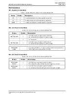
Page 9: ...k TB2 Name Pin No Description AC POWER H 1 external ac power supply positive terminal no connection when using a dc power supply 2 no connection AC POWER N 3 external ac power supply neutral terminal no connection when using a dc power supply AC POWER GND ac ground conductor Connect to the ground stud located at the lower right corner of the station s PCBA TB3 DC Power Terminal Block Table 3 DC Po...

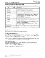
Page 10: ...ng 600 ohm or 15 kilohm termination configuration FOOTSWITCH 8 Positive side of auxiliary footswitch that operates as the local push to talk switch FOOTSWITCH 9 Negative side of auxiliary footswitch that operates as the local push to talk switch P1 Front Cover Wire Harness Connections Plug the front cover wire harness connector in at P1 see Figure 5 P3 Balanced Unbalanced Jumper Jumper P3 allows c...

Page 11: ...th the enclosure Do not omit any bolts 5 Torque the cover bolts to 30 ft lb 41 N m NOTE Refer to the Killark installation operation and maintenance data sheet enclosed with the unit for additional information Operation The station has an on off volume control switch and a push to talk switch 1 Turn the unit on or off and adjust the volume level in the listen mode using the on off volume control sw...

Page 12: ...lking Release the switch to deactivate the microphone and return the unit to listen mode Master Slave System A master station controls the talk listen function of the slave units through external control wiring in the master slave configuration Slave stations are in talk mode allowing the master station to monitor the slave s audio when the master station is in listen mode push to talk not active ...

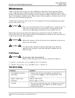
Page 13: ... inspection and a good preventive maintenance program will increase the reliability of the GAI Tronics station The GAI Tronics Field Service Department can formulate a service contract suited to specific needs for preventive maintenance WARNING Before performing any of the following preventive maintenance steps remove all power from the station CAUTION To reduce the risk of ignition of hazardous a...

Page 14: ... No 18 AWG two pair Specifications AC Power Voltage 120 V ac 50 60 Hz Power consumed at nominal Off mute 6 VA 1 8 W Standby 7 2 VA 3 6 W Maximum speaker out 30 VA 27 W DC Power Voltage 12 V dc Power consumed at nominal Off mute 0 3 W Standby 3 W Maximum speaker out 20 W Amplifier PCBA Frequency response 300 Hz 8 kHz 3 dB Audio output 8 0 W Audio THD distortion 1 maximum 8 W output Hum Noise 1 maxi...

Page 15: ... D When using auxiliary microphone and or footswitch Hazardous locations Class I Div 1 Group D Model 400 006 RigCom Station NRTL listed USA Hazardous locations Class I Div 1 Groups B C D When using auxiliary microphone and or footswitch Hazardous locations Class I Div 1 Group D Appendix A Interfacing a Model 400 005RigCom Station to EZ Page Stations The Model 400 005 RigCom Station operates as an ...

Page 16: ...4 561A docx 04 22 The following are wiring diagrams are for the different configurations of a RigCom EZ Page system Figure 10 Master Slave Unbalanced Configuration with the Model 400 005 as Master Figure 11 Master Slave Unbalanced Configuration with the Model 400 005 as Slave Figure 12 Unbalanced Common Line Configuration ...

Page 17: ...P Standard IOMs Current Release 42004 Instr Manuals 42004 561A docx 04 22 Figure 13 Master Slave Balanced Configuration with Model 400 005 as Master Figure 14 Master Slave Balanced Configuration with Model 400 005 as Slave Figure 15 Balanced Common Line Configuration ...

Page 18: ... of the Contractor s personnel from the work site Re performance of services shall be Buyer s sole and exclusive remedy and in no event shall GAI Tronics warranty obligations with respect to services exceed 100 of the total cost of the services provided hereunder Warranty Periods Every claim by Buyer alleging a defect in the goods and or services provided hereunder shall be deemed waived unless su...

Reviews: