Pub. 42004-561A
400-005 and 400-006 RigCom Stations
Page 6 of 16
P:\Standard IOMs - Current Release\42004 Instr. Manuals\42004-561A.docx
04/22
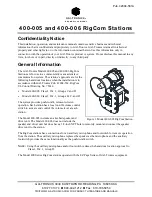
Figure 5. RigCom Station PCBA
5.
Attach the wires to the terminal blocks, on the PCBA, within the enclosure (see Figure 5 and the Field
Connections section for connection points and descriptions).
6.
If using the 10438-002 Auxiliary Microphone Assembly
: Connect the assembly to the station at
terminal block
TB4-1
(
+
) and
TB4-2
(
−
), and the shield to
TB4-5
, if used.
The maximum distance from the station is 50 feet using No. 18 AWG wire.
7.
If using the 51052-003 Auxiliary Footswitch Assembly
: Connect the assembly to the station at
terminal block
TB4-8
(
+
) and
TB4-9
(
−
), and the shield to
TB4-5
, if used.
The maximum distance from the station is 50 feet using No. 18 AWG wire.
System Line Balance
Each system requires termination of the audio pair wires with a 1-kilohm, 1-watt resistor assembly,
included with each unit. Install the line balance resistor assembly in a (
customer supplied
) junction box.
N
OTE
:
Use only one line-balance resistor assembly per system.
Install the resistor assembly in a (
customer supplied
) junction box that is close to the center of the system
when cable runs approximately 4000 feet (1219 m) or longer are used (see Figure 6 and Figure 7).


