background image

Pub. 42004-566A 

TempSense Models TS200/TS200W 

Page 3 of 9 

P:\Standard IOMs - Current Release\42004 Instr. Manuals\42004-566A.docx 

03/21 

Wall Mount 

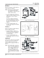
Mount the TempSense TS200/TS200W to a 
wall as follows (see Figure 4): 

N

OTE

:

  GAI-Tronics recommends spacing 

the TempSense Model TS200 
approximately ¼ inch from any flat 
surface to allow air flow. 

1.


Secure the mounting plate (

TS200

: see 

Figure 6, 

TS200W

: see Figure 7) to a flat 

surface using (

customer supplied

hardware. 

Use the four VESA mount holes to 
secure the mounting plate to the wall.  
No. 8 screws fit through the 0.190-inch 
threaded VESA mounting holes (see 
Figure 4). 

2.


Secure the TS200/TS200W to the 
mounting plate using the four included 
#6-32 screws. 

Pole Mount 

Mount the TempSense TS200/TS200W to a 
pole (see Figure 5) as follows: 

1.


Secure the TS200 (see Figure 6) or 
TS200W (see Figure 7) mounting plate, 
to a pole using (

customer supplied

worm-drive clamps 

2.


Secure the TS200/TS200W to the 
mounting plate using the four included 
#6-32 screws. 

VESA Mount 

Attach a VESA (video electronics standards 
association) mount to the mounting plate 
with the included #10-24 screws and 
washers (

TS200

: see Figure 6, 

TS200W

: see 

Figure 7). 

N

OTE

:

  The TS200/TS200W includes four 

#10-24 × 0.38-inch long screws to 
attach a customer supplied VESA 
mount.  Do 

not

 use any screws 

other than the included #10-24 
screws to attach the VESA mount 
to the TS200/TS200W’s mounting 
plate. 


Figure 4.  Wall-Mount Detail 


Figure 5.  Pole-Mount Detail 


Figure 6.  Mounting Plate Detail (Model TS200) 

Summary of Contents for GAI-TRONICS TempSense TS200

Page 1: ...WWW GAI TRONICS COM FOR PRODUCT LITERATURE AND MANUALS Confidentiality Notice 1 General Information 1 Installation 2 Camera Location 2 Wall Mount 3 Pole Mount 3 VESA Mount 3 Stand Mount 4 Connection...

Page 2: ...eration of your GAI Tronics product or system This manual may not be disclosed in any form in whole or in part directly or indirectly to any third party General Information The TempSense Models TS200...

Page 3: ...closer to the camera Camera Location Locate the TempSense TS200 TS200W so that people in a queue individually pass through the two cameras shared FOV while facing the cameras Each subject scanned shou...

Page 4: ...mounting plate using the four included 6 32 screws PoleMount Mount the TempSense TS200 TS200W to a pole see Figure 5 as follows 1 Secure the TS200 see Figure 6 or TS200W see Figure 7 mounting plate t...

Page 5: ...If the IR sensor LED does not flash press the sensor into its socket using a soft cloth then reboot the device The Model TS200 boots up and is ready for configuration see the Configuration section or...

Page 6: ...and time see Table 4 5 Configure all settings and click APPLY CHANGES AND RESTART The unit reboots with the configured settings NOTE If the network mode is DHCP but no DHCP server exists the unit fal...

Page 7: ...rts after the measured temperature drops below the threshold temperature 0 100 5 seconds Offset The value to add to or subtract from the temperature measured by the TempSense 10 to 10 F 0 F 6 to 6 C 0...

Page 8: ...Pv4 address or FQDN string 0 0 0 0 time_zone The offset from UTC Select the offset from UTC using the roll box control Calibration 1 Place an object of known temperature in the field of view of the TS...

Page 9: ...rcent Allow the TS200 TS200W to operate in the testing environment for 10 30 minutes to adjust to its environment before scanning personnel Subject Preparation To obtain accurate skin temperatures ens...

Page 10: ...andard IOMs Current Release 42004 Instr Manuals 42004 566A docx 03 21 Specifications Electrical Power TS200 PoE TS200W 120 V ac Mechanical Dimensions 7 26 H 5 76 W 1 5 D in 184 4 146 3 38 1 mm Weight...

Reviews: