System Configuration __________________________________________________________________
RF-MCGARDPRO
Hubbell Power Systems, Inc.
–
RFL™
Products
July 1, 2022
©2022 Hubbell Incorporated
4-26
Input Test
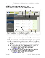
Menu location: Test > Inputs. Select the input to be tested.
The following web page verifies the correct function of the relay inputs.
1
2
3
4
5
6
Represents the Input
Number of the I/O module
Description of inputs as
entered on the Label Enable
Configuration webpage
Figure 4-26. Input Test
1.
TB#/State:
Indicates the terminal block number of the input function and whether
voltage is applied to the input terminals. This can be thought of as ‘before’ the logic bit
associated with the input. This field is updated dynamically.
2.
Logic State:
Indicates the state of the logic bit associated with the input. This can be
thought of as ‘after’ the terminal block state. This field is updated dynamically.
3.
Action:
This drop-down menu will allow the tester to set the inputs to the following
modes:
•
Normal:
This is the normal operating condition for the input. The input status is
placed on the logic bus.
•
Hold:
This will lock the input to its current state.
•
Off/On:
Sets the input logic state to 0/1 independent of the terminal block state.
The inputs mode will only change after the
“Execute Action”
button has been pressed.
The module will issue a minor alarm if any input function is set to anything other than
normal.


