Digital Teleprotection __________________________________________________________________
RF-MCGARDPRO
Hubbell Power Systems, Inc.
–
RFL™
Products
July 1, 2022
©2022 Hubbell Incorporated
6-7
1
2
3
4
5
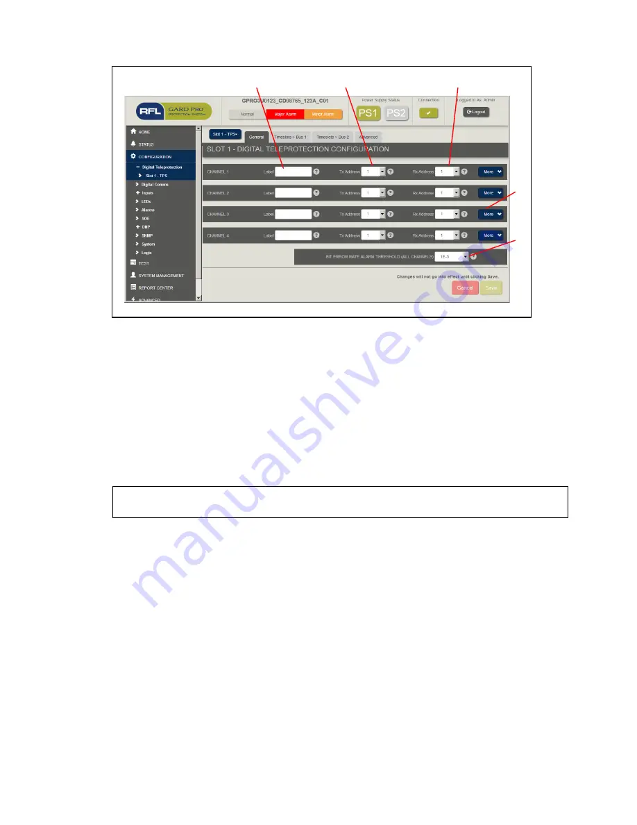
Figure 6-6. Digital Teleprotection Configuration – General Tab
The parameters and descriptions below apply to all four teleprotection channels, with some
exceptions noted.
1.
Label
: This is a 64-character label the user enters as a reference in the interface.
2.
Tx Address
: This is the address transmitted with each teleprotection message.
3.
Rx Address
: This is the expected receive address. To receive properly a Receiver must
see its correct address according to the programming on this page. It will reject a message
if the addressing is corrupt and/or doesn’t match.
Note
: Tx and Rx addresses must be unique across the system to avoid addressing
conflicts.
4.
“More”:
Click this button to expand the content behind/below the main channel settings
bar. Each channel has this button. Its operation is described more in the next screenshot.
5.
Bit Error Rate Alarm Threshold:
This is an alarm threshold for the Bit Error Rate
measurement. It is calculated by the Teleprotection module for each channel, but the
alarm threshold applies to all channels.
All data in user-entered fields (not drop-downs or controls) are validated according the
range/increment specified. Any fields changed to a valid entry will be flagged “green” and any
fields changed to an invalid entry will be flagged “red” and a warning presented beside the
field. For typical existing GARD Pro behavior – see “Config > PLC” pages for reference.

