Digital Teleprotection __________________________________________________________________
RF-MCGARDPRO
Hubbell Power Systems, Inc.
–
RFL™
Products
July 1, 2022
©2022 Hubbell Incorporated
6-12
•
A comms interface may only be assigned to one Bus. If it is used on Bus 1 it is not
available in the drop-down lists on Bus 2, and vice-versa.
•
For RS-449/X.21/V.35, C37.94, and Long-Haul Fiber: these interfaces may be
programmed to more than one timeslot only if the timeslots are continuous. TS1, TS2,
TS3 is OK but TS1, TS2, TS4 is not. If an interface is chosen on TS1, then on TS5, the
intervening timeslots will be automatically populated with that interface.
•
If the Async interface has any channel programmed to a baud rate of 38.4 kbps, then the
Function option “Async Ch1 & Ch2” is no longer available.
•
If “Async Ch1 & Ch2” is selected, “Async Ch1” and “Async Ch2” are no longer
available.
•
If two functions are selected having discontinuous timeslots, the timeslots in-between
which have no function assigned become “Idle”.
For example, if function/interface TS1 = TPS Ch1 and C37.94, function/interface TS5 =
TPS Ch2 and RS-449 functions TS2, TS3 and TS4 become “Idle”.
•
Comms interfaces must be continuous on the bus. You cannot set C37.94 on TS1, and
TS5 with nothing in-between. In this scenario, once C37.94 is selected on TS5, TS2,
TS3, and TS4 are automatically populated with “C37.94”. Any of the C37.94 timeslots
with no function will be automatically populated with “Idle”. See Section 7.3.3, page 7-
18 for an example.
•
A function must have a comms interface associated with it, and vice-versa.
Note
: Until a function/interface pair has been selected for a timeslot, that timeslot is
tagged “red” for invalid programming. “Save” cannot be performed in this state.
•
Service Channels cannot be mapped over a G.703 interface, since the function requires
framing to be enabled, and G.703 runs only at 64 kbps
Timeslot Configuration Example
To assign the Digital Teleprotection with a Digital Communications interface and timeslot do
the following:
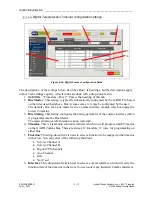
1.
Follow the lettered steps to navigate to the Timeslot bus:
a
c
d
b
a.
Select CONFIGURATION on the navigation pane. This expands to show the
subordinate items.
b.
Expand the “Digital Teleprotection” item. The system displays the Digital
Teleprotection modules available.
c.
Select the “Slot # - TPS” for the module to be configured.
d.
Select the “Timeslot > Bus #” tab. The system displays the “TIMESLOT
MAPPING > BUS #” page. “#” is the number of the selected bus.


