Digital Communications Interfaces ________________________________________________________
RF-MCGARDPRO
Hubbell Power Systems, Inc.
–
RFL™
Products
July 1, 2022
©2022 Hubbell Incorporated
7-23
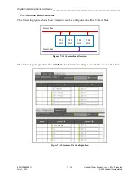
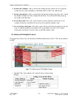
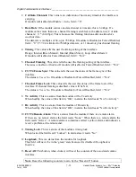
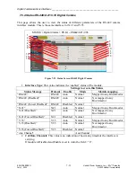
The diagram shows a computer able to control Stations G2 and G3 across the service channels
beyond Station G1.
G1
NE T
RE SET
PWR
GAR D
PRO
G2
G3
ChA x.x.x.110
Note
: The RED line is a timeslot configured for a D-TPS function.
Service channel use does not interrupt regular function.
ChB x.x.x.120
ChB x.x.x.130
ChA x.x.x.140
GA RD PRO
NE T
RE SET
PWR
GAR D
PRO
Figure 7-18. Service Channel example
When done, the addresses will be like the example in the following table.
Table 7-1 Example Service Channel Settings
Service Channel A Service Channel B
G1
x.x.x.10
Service Channel IP
x.x.x.110
x.x.x.120
Remote Rear Netmask
255.255.x.x
255.255.x.x
Remote Rear IP
x.x.x.20
x.x.x.30
Remote IP access thru Front Port
192.168.1.3
192.168.1.4
G2
x.x.x.20
Service Channel IP
x.x.x.130
Remote Rear Netmask
255.255.x.x
Remote Rear IP
x.x.x.10
Remote IP access thru Front Port
192.168.1.4
G3
x.x.x.30
Service Channel IP
x.x.x.140
Remote Rear Netmask
255.255.x.x
Remote Rear IP
x.x.x.10
Remote IP access thru Front Port
192.168.1.3
Note
:
Service Channel A must always be configured to communication with Service Channel B.


