Digital Communications Interfaces ________________________________________________________
RF-MCGARDPRO
Hubbell Power Systems, Inc.
–
RFL™
Products
July 1, 2022
©2022 Hubbell Incorporated
7-26
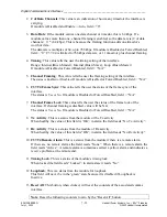
7.5.1 Status T1/E1 Digital Comms
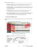
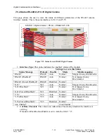
This page allows the user to view the status of different parameters of the T1/E1 comms
interface module.
1
2
9
3
4
5
6
7
8
10
11
12
13
14
15
16
17
18
19
STATUS > Digital Comms > Slot # - T1/E1
Figure 7-20. Status Screen T1/E1 Digital Comms
1.
Interface Type
: For the T1/E1 module this value is a combination of the “Mode”
setting from “Configuration > Digital Comms (T1/E1)” as well as the “Enable” status of
the module.
Settings to create this Status
Status Message
Mode
Enable
T1/E1 Mapping
“T1”
T1
Auto
Mapped to any Bus/timeslot
“T1 (Disabled)”
T1
Auto
Not mapped to any Bus/timeslot
“T1 (Forced Disabled)”
T1
Disabled
None
“E1”
E1
Auto
Mapped to any Bus/timeslot
“E1 (Disabled)”
E1
Auto
Not mapped to any Bus/timeslot
“E1 (Forced Disabled)”
E1
Disabled
None
2.
# of Data Channels
: This value is an indication of how many timeslots the interface is
carrying. Value is 0-12.
If module is Disabled and Enable = Auto, field = “0”.
If module is Forced Disabled, field = “N/A”
3.
Data Rate
: This is a fixed value for the T1/E1 module.
The field reads 1.544 for T1 and 2.048 for E1.
If module is Disabled or Forced Disabled, field = “0”
4.
Timing
: This value tells the user the timing setting of the interface.
Range: Internal (Bus n Master), Loop (Bus n Master)
If module is Disabled or Forced Disabled, field = “N/A”

