System Description ____________________________________________________________________
RF-MCGARDPRO
Hubbell Power Systems, Inc.
–
RFL™
Products
July 1, 2022
©2022 Hubbell Incorporated
2-12
2.5.3.7.1 Built In I/O port
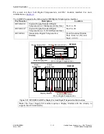
The illustration below shows the location of the built-in communication module on the 3 and 6U
chassis. For more information on the connector pinouts see section
Output Module (Slot 4)
+-
+-
Input Module (Slot 2)
3U Chassis
Rear View
Comms (Built In)
Power Supply I/O
System I/O (Slot 11)
Analog Input (Slot
1 and 2 typical)
6U Chassis
Rear View
Additional Comms (Typical)
Input/Output
Comms (Built In)
Power Supply I/O
M AJOR
-
+
S12
M INOR
-
+
S13
5 00 8 5 5
RS-4 49
X.2 1
V.3 5
24
22
23
20
21
18
19
3
14
16
17
15
13
11
12
9
10
7
8
5
6
4
2
1
24
22
23
20
21
18
19
3
14
16
17
15
13
11
12
9
10
7
8
5
6
4
2
1
V.3 5
X.2 1
RS-4 49
1PPS
IRIG-B
GPS
ETH ERN ET
5
RS-485
MOD BUS
DNP
6
2
3
1
4
SYSTEM I/O
RS-232
500420
5 00 8 5 5
V.3 5
X.2 1
RS-4 49
24
23
22
21
17
19
20
18
16
15
14
13
24
23
22
21
17
19
20
18
16
15
14
13
24
23
22
21
17
19
20
18
16
15
14
13
P OWE R S UPP LY 1
P OWE R S UPP LY 2
500875
TX
RX
C37.94
Figure 2-10. Location of Synchronous multi-protocol interface
Extraction Tool:
An extraction tool is included on the rear of the chassis. This tool is used when removing the I/O
Base Module as shown in
Digital TPS (optional):
The Digital TPS module provides digital teleprotection functionality for use with digital
communications interfaces. Each module supports 4 independent 64kps channels, each including
8 bi-directional functions for a total of 32 functions per module. The digital teleprotection module
is available in two types, combined with the system display, or as a separate module. A GARD


