Installation __________________________________________________________________________
RF-MCGARDPRO
Hubbell Power Systems, Inc.
–
RFL™
Products
July 1, 2022
©2022 Hubbell Incorporated
3-10
3.5.8 System timing
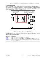
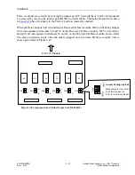
Shown below are the jumper locations on the 3U System I/O Board for IRIG-B applications.
Please note that when the GPS plug-on module is installed J2 (not shown) on the GPS Module
can be set to grounded or isolated depending on the jumper positions. When in the grounded
position the shield of the co-axial cable will be grounded.
Special application only, IRIG-B
signal through rear RS-232 port
Jumper Locations/GPS
Module Locating
J 11
J 10
1
1
2
2
15
15
16
16
J 3 J12
IRIG
NORM
NORM
IRIG
J6
J9
J4
J 7
J 8
J 13
J 14
1
1
SPARES
1
2
15
16
1
2
15
16
UNMOD
MOD
NON E
50 OHM
600 OHM
TERM
ISOLATED
GRO UNDED
50 OHM
NON E
600 OHM
Figure 3-5. 3U Chassis, System I/O Board Jumper Locations
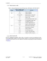
The following subsections list the jumper settings required when using the IRIG-B. The 6U
chassis is arranged in a similar manner.
Subsection
Description
IRIG-B is used without the GPS plug-on module
IRIG-B is used without the GPS and second HPS/RFL GARD Pro system units
IRIG-B signal accessed through the rear RS-232 port on the HPS/RFL GARD
Pro system I/O Module


