Power Line Carrier ____________________________________________________________________
RF-MCGARDPRO
Hubbell Power Systems, Inc.
–
RFL™
Products
July 1, 2022
©2022 Hubbell Incorporated
5-67
Continued……
Reference
Designation
Component
Function
J25
Jumper
Selects 4W mode or Loopback mode.
J11, J12 and
J23
Jumper
All three of these jumpers must be set to 2W to select 2W mode.
All three of these jumpers must be set to 4W to select 4W mode.
R10
Potentiometer
Adjusts the RX Output level.
TP1
Test point
Connect the low or common side of test equipment to this test point
when monitoring TP2 or TP3.
TP2
Test point
TX monitor high, test point.
TP3
Test point
RX monitor high, test point.
J16
Jumper
Used for factory testing. In normal operation this jumper is not
installed.
5.6.6 RX Filter
The function of the Rx Filter is to prevent harmonics and noise from coming into the 8790 Pro
from the power line that is out of the bandwidth of the filter. The bandwidth of the Rx Filter can
be set to either 8kHz or 16kHz using two programmable jumpers on the board. The filter center
frequency is tunable from 24kHz to 496kHz using programmable jumpers. The outer edges are
20kHz and 500kHz. The 8kHz bandwidth is used for most applications. The Rx Filter Board is
optional and is typically replaced with the Rx Connection Board.
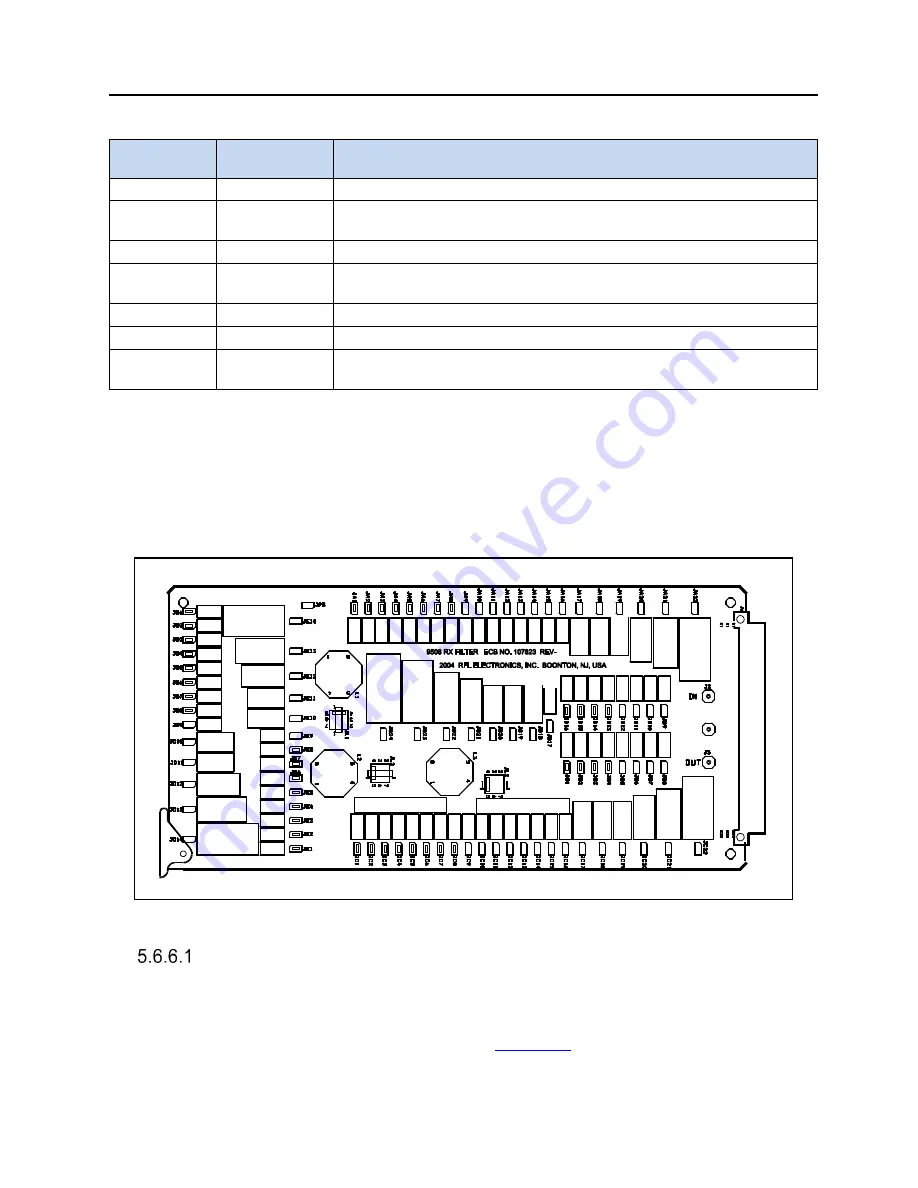
Figure 5-44. Location of Jumpers on the RX Filter board
Setting Jumpers on the RX Filter and RX Filter Tuning
The RX Filter has many jumpers (about 100) that must be configured for proper system operation.
These jumpers allow a user to select the bandwidth, which can be either 8kHz or 16kHz, and to
tune the center frequency, which can be from 24kHz to 496kHz (the outer edges are 20kHz and
500kHz). The location of these jumpers is shown in
. Tuning the filter is done per the
Microsoft Excel® Worksheet “9508 RX Filter Programming Sheet.xls” supplied with the
Customer CD.


