Digital Communications Interfaces ________________________________________________________
RF-MCGARDPRO
Hubbell Power Systems, Inc.
–
RFL™
Products
July 1, 2022
©2022 Hubbell Incorporated
7-25
7.5
Digital Communications Status
These pages, in general, allow the user to view the status of different parameters of the
communications interface modules. Each module has its own page and its own sidebar menu
item. The user can select between modules by using the sidebar menu or by using the drop-
down next to the tabs.
The menu item and page are available only when a comms module of that type is installed
somewhere in the chassis, or when a display module is installed which is equipped with Digital
Teleprotection and capability to drive power supply comms interface, such as a 500410-5 or
500410-7.
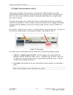
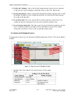
Each “Status > Digital Comms > Slot n – (Comms Interface)” page has three tabs – the status of
the selected Comms Interface, and a Status tab for Bus 1 and another for Bus 2.
1
2
Figure 7-19. Status pages
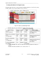
The status pages for the Digital Comms modules share the following identifying fields:
1.
“
SLOT n – {Module Type} STATUS
”: This is a display-only value which is the
heading of this tab. It takes the format “Slot n – {Module Type} STATUS” where n is
the physical slot location of the Teleprotection module and {Module Type} is the type
of card which is installed in that slot.
2.
User Label
: This field shows the user-entered label from the interface’s configuration
page.
Note
: ASYNC Digital Comms does NOT have a label.

