Digital Communications Interfaces ________________________________________________________
RF-MCGARDPRO
Hubbell Power Systems, Inc.
–
RFL™
Products
July 1, 2022
©2022 Hubbell Incorporated
7-32
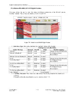
7.5.4 Status RS-449/X.21/V.35 Digital Comms
This page allows the user to view the status of different parameters of the RS-449 comms
interface module. This is the same interface for X.21 and V.35.
1
2
9
3
4
5
6
7
8
10
11
12
14
15
13
16
STATUS > Digital Comms > PS I/O
– RS449/X.21/V.35
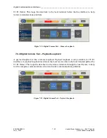
Figure 7-23. Status Screen RS-449 Digital Comms
1.
Interface Type
: This value indicates the ‘enabled’ status of the module.
Settings to create this Status
Status Message
Protocol
Enable
Mode
Module mapping
“RS-449”
RS-449
Auto
Normal
Mapped to any Bus/timeslot
“RS-449 (Disabled)”
RS-449
Auto
Normal
Not mapped to any
Bus/timeslot
“RS-449 (Forced Disabled)” RS-449
Disabled
Normal
“X.21”
X.21
Auto
Normal
Mapped to any Bus/timeslot
“X.21 (Disabled)”
X.21
Auto
Normal
Not mapped to any
Bus/timeslot
“X.21 (Forced Disabled)”
X.21
Disabled
Normal
“V.35”
V.35
Auto
Normal
Mapped to any Bus/timeslot
“V.35 (Disabled)”
V.35
Auto
Normal
Not mapped to any
Bus/timeslot
“V.35 (Forced Disabled)”
V.35
Disabled
Normal
“Aux Channel”
Aux Channel
2.
# of Data Channels
: This value is an indication of how many timeslots the interface is
carrying.
If module is Disabled and Enable is set to Auto the field = “0”.


