Installation __________________________________________________________________________
RF-MCGARDPRO
Hubbell Power Systems, Inc.
–
RFL™
Products
July 1, 2022
©2022 Hubbell Incorporated
3-12
Rear of GARD unit 1
Rear of GARD unit 2
GPS
GPS Receiver
Substation
IRIG-B out
IRIG-B in
The second GARD unit must have
the jumpers set on the System I/O
module as shown.
Figure 3-6. IRIG-B with GPS
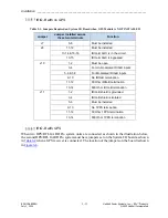
Table 3-2. System I/O jumper Settings with IRIG-B and GPS
Jumper
Jumper Installed Across
these two Terminals
Jumper Position
J7
5-6
IN
- Must be installed
J8
11-12
IN
- Must be installed
13-15
IN
- IRIG-B, AGC is bypassed
J10
3-4
IN
- For Unmodulated IRIG-B inputs
13-14
IN
- 600 Ohm IRIG-B termination
J11
1-2
IN
- IRIG-B shield is grounded
5-6
IN
- Must be installed
13-14
IN
- 600 Ohm 1PPS termination
Note:
All other jumpers should be removed (no connection).
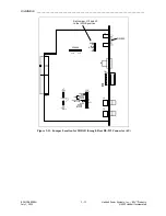
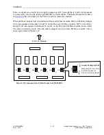
IRIG-B Signal, Through Rear RS-232 Port
There may be a situation where a customer requires an IRIG-B signal accessed through the rear
RS-232 port on the HPS/RFL GARD Pro system I/O Module. To access the IRIG-B signal
through the RS-232 port set jumpers on the System I/O board as shown in
The pins are used according to the following:
•
Pin 5 = Signal Ground
•
Pin 4 = IRIG-HI
•
Pin 6 = IRIG-LO
All other pins = "Not Used"


