Installation __________________________________________________________________________
RF-MCGARDPRO
Hubbell Power Systems, Inc.
–
RFL™
Products
July 1, 2022
©2022 Hubbell Incorporated
3-13
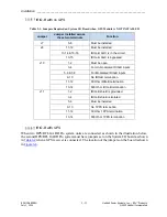
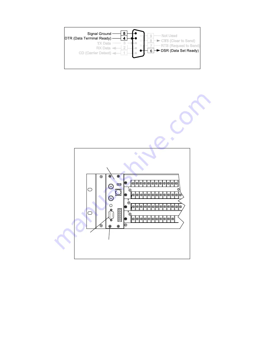
DB-9 Male
RS-232
Figure 3-7. RS-232 Pin-Outs
3.5.8.3.1 Setting Procedure
1.
Before accessing the System I/O board on either the HPS/RFL GARD Pro system 3U or
6U chassis power down the GARD unit.
2.
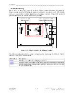
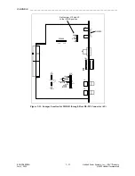
Jumper J3 and J12 on the System I/O board need to be set to the IRIG-B position. This
will allow IRIG-B signals to be brought into the GARD through pin 4 and 6 on the RS-
232 connector.
3.
Refer to the following figure for the location of Jumper J3 and J12. The System I/O
board is easily removed from the chassis as shown.
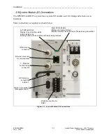
Partial view of rear of 3U GARD
chassis showing System I/O board
System I/O board
RS-232
Connector
Loosen 4-screws and
slide out module to
access jumpers
Figure 3-8. Removing System I/O Board (3U)
4.
After setting the jumpers, re-seat the applicable module and tighten the screws, do not
over tighten.
5.
Re-apply power to the GARD.
See the following page for jumper locations on the 3U and 6U Chassis.


