Installation __________________________________________________________________________
RF-MCGARDPRO
Hubbell Power Systems, Inc.
–
RFL™
Products
July 1, 2022
©2022 Hubbell Incorporated
3-21
3.7.1 Input Unit
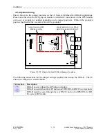
The Input Unit (RF-500805) has six inputs, which can accommodate 24Vdc, 48Vdc, 125Vdc or
250Vdc. These voltages are selectable by a user via jumpers (J12, J11, J10, J9, J8 and J7) on the
Input Unit.
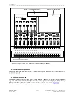
shows the location of these jumpers.
A voltage is selected by inserting a jumper. The Input Unit in
J7 through J12. When the input unit is installed in a Discrete I/O Base module, J12 on the Input
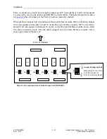
Unit corresponds to terminals 23 and 24 on the Discrete I/O Base module, J11 on the Input Unit
corresponds to terminals 22 and 21 on the Discrete I/O Base module, and so forth. The same
correlation exists when the unit is plugged onto a Comms I/O Base module. This is shown
pictorially in
GARD 8000 INPUT UNIT
J12
J11
J10
J9
J8
J7
2
4
V
2
4
V
2
4
V
2
4
V
2
4
V
2
4
V
4
8
V
4
8
V
4
8
V
4
8
V
4
8
V
4
8
V
1
2
5
V
1
2
5
V
1
2
5
V
1
2
5
V
1
2
5
V
1
2
5
V
2
5
0
V
2
5
0
V
2
5
0
V
2
5
0
V
2
5
0
V
2
5
0
V
Figure 3-16. Component side of Input Unit (RF-500805)
3.7.2 Redundant Input Unit
The Redundant Input Unit (RF-500805-1) is used to provide redundant protection of the opto-
isolators. The configuration and jumper settings are identical to the Input Unit.


