®
Wiring Device-Kellems
Hubbell Incorporated (Delaware)
185 Plains Road
Milford, CT 06460-8897
(203) 882-4800
PD1718
(Page 1)
Rev. 07/07
English
GENERAL INFORMATION
1.
CAUTION:RISK OF ELECTRIC SHOCK. Disconnect power before installation or maintenance.
2.
NOTICE
: For installation only by a qualified electrician in accordance with national and local
electrical codes and the following instructions.
3.
CAUTION: USE COPPER CONDUCTORS ONLY. Use stranded conductors only.
4. Check that the device’s type and rating are suitable for the application.
5. Select the conductor size from National Electrical Code
®
Table 400-5B or Canadian Electrical
Code Table 12A.
Rated for use with Type G, W portable cords or equivalent with COPPER conductors only.
6. The plug is rated Type 3,4, and 4X when connected to an equivalently rated connector or receptacle
when using the locking ring. The receptacle and connector are rated Type 3,4, and 4X when the cap
is in the closed position or connected to an equivalently rated plug when using the locking ring.
ELECTRICAL RATING:
Max. Voltages: 600 VAC, 250 VDC.
PLUG, CONNECTOR & INLET INSTALLATION
1. Check the rating on the label to insure that it is correct for the installation.
2. Select cable of suitable ampacity and temperature rating (see Table 1).
3. Select cord end with proper conductor color orientation that matches terminal location. Shear
cord cleanly. Do not strip away cord jacket or remove
conductor insulation at this time.
4.
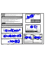
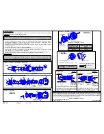
To disassemble Connector (see figure 1)
• Remove ground screw (12).
• Remove retaining ring(1) and interior assembly(2)
from plug body(3).
• Loosen clamp guide set screw(4) and turn clamp guide
assembly(5) to remove from plug body.
To disassemble Plug (see figure 2)
• Remove adapter set screw(12) and connector
adapter(13) from connector nose(17).
• Remove mounting screws(16), ground strap(14), keying ring(15) and interior assembly(2).
• Loosen clamp guide set screw(4) and turn clamp guide assembly(5) to remove from adapter(13).
To disassemble Inlet (see figure 3)
• Remove mounting screws(16), ground strap(14) w/screw (for Style 2), keying ring(15) and
interior assembly(2).
• Slide keying ring(15) over power cable.
Do not disassemble interior assembly.
*For plugs & connectors
*5. Slide clamp guide(5) with cable clamps(6) (see figure 4 for proper inserts) and one grommet
washer(7) over power cable. (Select proper grommet washer with respect to cable size).
*6. See figure 5 for cable gaging strip to determine how many "inner layers" of the onion skin
grommet(8) are to REMAIN or remove "inner layers" until the grommet slips over power cable.
Remove one layer at a time by pushing through and tearing off.
*7. Place onion skin grommet(8) over power cable. For plugs place plug body(3) with locking
ring(9) and for connectors, place keying ring(15) over power cable.
8. Strip cable jacket 4" and each conductor 1 1/4".
9. Twist wire strands together on each conductor.
DO NOT TIN CONDUCTORS
.
10.
NOTE: Crossing one ungrounded conductor (Line) over the grounded conductor (Neutral)
may be necessary with five-wire devices.
11. Insert conductors into the proper terminals according to the established wiring pattern. The grounding
terminal (earthing) is indicated by a green marking, a "G" or the earthing symbol. The neutral
terminal (grounded) is to be marked with PERMANENT white coloration by installer in accordance
with National Electrical Code
®
Section 200-9. See figure 6 for Style 1 and Style 2 wiring.
12. Tighten terminal screws to a torque of 17 lb•ft.
13.
TAKE CAUTION THAT THERE ARE NO STRAY WIRE STRANDS.
14.
To reassemble Connector (see figure 1)
• Slide interior assembly into(2) into plug body(3) aligning the internal plug body key and insulator
key slot. Place retaining ring(1) into the plug body slot.
• Install ground screw (12). Torque to 24 lb.-in.
To reassemble Plug (see figure 2)
• Slide interior assembly(2) into connector nose(17), align keying ring(15) with interior key slot,
and align mounting holes of ring with connector nose.
• Install mounting screws(16) and ground strap(14). Screw adapter(13) onto connector nose(17)
and torque adapter set screw (12) to 15 to 20 lb•in.
To reassemble Inlet (see figure 3)
• Slide interior assembly(2) into receptacle housing. Place and align keying ring(15) with the
key slot in the interior and align mounting holes with receptacle.
• Install mounting screws and ground strap with screw (for Style 2).
*For Plugs & Connectors
*15. Slide onion skin grommet(8) down power cable into plug body(3). Place grommet washer in clamp
guide and screw clamp guide onto plug body. Torque clamp guide set screw(4) to 15 to 20 lb•in.
*16. Torque cable clamp screws (11) to a minimum of 50 lb•in, alternating sides to prevent binding.
For Inlets
Mount with gasket(18) using bolts(20) and torque to 30 to 40 lb•in. There must be a tight seal
between housing and back box to assure a weatherproof, oil tight and hosedown water tight fit.
INSUL
INSUL
INSUL
INSUL
INSULGRIP
GRIP
GRIP
GRIP
GRIP
®
®
®
®
®
PIN & SLEEVE
PIN & SLEEVE
PIN & SLEEVE
PIN & SLEEVE
PIN & SLEEVE
PL
PL
PL
PL
PLUG
UG
UG
UG
UG,,,,, CONNECT
CONNECT
CONNECT
CONNECT
CONNECTOR & INLET
OR & INLET
OR & INLET
OR & INLET
OR & INLET
REVERSE SERVICE 200 Amp • Style 1 & 2
REVERSE SERVICE 200 Amp • Style 1 & 2
REVERSE SERVICE 200 Amp • Style 1 & 2
REVERSE SERVICE 200 Amp • Style 1 & 2
REVERSE SERVICE 200 Amp • Style 1 & 2
INST
INST
INST
INST
INSTALLA
ALLA
ALLA
ALLA
ALLATION
TION
TION
TION
TION
OPERA
OPERA
OPERA
OPERA
OPERATION
TION
TION
TION
TION
MAINTEN
MAINTEN
MAINTEN
MAINTEN
MAINTENANCE
ANCE
ANCE
ANCE
ANCE
TABLE 1
DEVICE
AWG/
CORD O.D.
TYPE
COND
RANGE (in)
200 Amp
1/3 to
1.00 - 2.50
Style 2:2P+G
250 kcmil/3
200 Amp
1/4 to
1.00 - 2.50
Style 1:3P
250 kcmil/4
Style 2:3P+G
200 Amp
1/5 to
1.00 - 2.50
Style 1:4P
250 kcmil/5
A wire pattern MUST be used so that the same color insulated conductor is put into the same
numbere contact opening in all plugs, receptacles & cable connectors in the system. This
requirement provides correct polarity for the system to avoid causing personal injury and/or
equipment damage.
CAUTION
DO NOT connect to power before conducting the following Electrical Tests:
• Test continuity of wiring to verify correct phasing and grounding connections.
• Measure insulation resistance to be sure the system does not have any short circuits or
unwanted grounds.
CAUTION
The equipment grounding path between the inlet housing and back box must be
established and verified. Star washers are included for use under the mounting bolt
heads to help achieve ground continuity.
CAUTION


