


position.
2. Push the test button on the individual GFCI
module. The unit should trip.
3. Push the reset button. The indicator light
should come on.
4. Repeat steps 2 & 3 for the remaining six
modules.
Models SDSB2 and SDTL2
only, equipped
with (1) 30 Ampere GFCI circuit breaker.
1. Push the test button. The unit should trip.
2. Reset the breaker by pushing handle to the
“OFF” position, then to “ON”.
If the unit does not trip when tested, or cannot
be reset after conducting the recommended
troubleshooting procedure, consult Hubbell
Incorporated, Milford, Connecticut.
TROUBLESHOOTING THE SPIDER II
The main power contactor within the SPIDER II
unit will trip whenever one or more of the
following abnormal conditions exist in the line
(supply) side circuit:
1. Either line (hot) conductor is transposed with
the neutral conductor.
2. Either line (hot) conductor is open
(disconnected).
3. There is an excessive voltage imbalance
between line 1 and line 2 circuits. This may
be the result of an open neutral conductor in
the supply circuit.
When the abnormal condition(s) in the supply
circuit is corrected, the unit may be reset for
normal use by completely removing and then
reapplying line power. It is recommended that
the GFI test procedure be repeated at this time.
When a GFI module trips, attempt to reset it by
pressing the reset switch, being careful to look
for possible danger to personnel. If the module
resets, the fault was momentary and has
cleared. If it trips again immediately, the fault is
still present and the GFI module is performing its
safety function. To locate the fault, disconnect
all loads and again try pressing the reset switch.
The module should reset. Reconnect the loads
one at a time. The module will trip when the
faulted load is reconnected. Inspect all tools,
appliances and extension cords in the faulted
load circuit, repairing or replacing any that are
not in good condition.
NOTE:
Tripping of a branch circuit breaker in
the models can only result from an overload or
short circuit condition in its individual load circuit.
When the fault in the load circuit is corrected
or removed, the circuit breaker can be reset
for normal use by turning handle to “OFF”
position and then to the “ON” position.
Models SDTL2 and SDSB2 only
A GFI circuit breaker will trip whenever one or
more of the following fault conditions exist in
its individual branch circuit:
1. A ground fault occurs (the leakage current
to ground exceeds 5 milliamperes).
2. The neutral conductor becomes grounded.
3. There is an overload or short circuit.
When a GFI circuit breaker trips, attempt to reset
it by turning its handle to the “OFF” position then
to the “ON” position. If it resets, the fault was
momentary and has cleared. If it trips again, the
fault is still present and the GFI breaker is
performing its safety function. To locate the
fault, disconnect all loads on the branch circuit
in question. (Note that this corresponds to only
one outlet on the SPIDER
®
II UNIT. A load of more
than one tool or appliance on a given branch
circuit can only be achieved using multiple outlet
taps, strips, or extension cords, or through a
feed-through receptacle(s) built into an
appliance). Reset the GFI breaker and reconnect
the loads one at a time. The breaker will trip
when the faulted load is reconnected. Inspect
all tools, appliances and extension cords in the
faulted circuit, repairing or replacing any that
are not in good condition.
NOTE:
If a GFI circuit breaker trips as the result
of an overload condition, it may not trip
immediately after the load has been disconnected
and then reconnected because the thermal
sensing element has cooled. For example, the
breaker is permitted to take up to one hour to trip
off when carrying 135 percent of its rated load
(40.5 amperes on a 30 amp circuit).
When the fault in the load circuit is corrected or
removed, the GFCI circuit breaker should be
reset for normal use.
APPLICATION NOTES
1. Tripping of individual branch circuit breakers
in any SPIDER II unit has no effect on
downstream units connected through the
30 amp outlet.
2. There is no overload protection for the 30
amp outlet.
3. When shutting down the temporary power
at the end of the working day, do so by
pressing the test button on the individual
modules on the SPIDER II unit and the individual
GFI breaker test buttons for models SDTL2,
SDSB2.
NUISANCE TRIPPING
All cables have some capacitive leakage.
In a 120 V system, there is a limit to the
length of cable which can be run before
sufficient leakage to ground will build up
causing a GFI to trip. In the Hubbell SPIDER
II system, however, capacative leakage in
the two power lines flows in opposite
directions. This design cancels the
capacative leakage effect, and there is no
theoretical limit to the length of
interconnecting cable runs between SPIDER
II units. Individual 120 volt branch circuit
load cords, however, should be limited to
250 feet in length.
MAINTENANCE & REPAIR
Replacement
Part
Manufacturer
Device
Description
Number
HUBBELL
Receptacle
20 A 125 V Twist-Lock
HBL2310SW
HUBBELL
Receptacle
20 A 125 V Straight Blade
HBL53R61
HUBBELL
Receptacle
30 A 250 V Twist-Lock
HBL2620SW
HUBBELL
Receptacle
30 A 125/250 V Twist-Lock
HBL2710
HUBBELL
Inlet
30 A 125/250 V Twist-Lock
HBL2715SWR
HUBBELL
Supervisory Module
Polarity Supervisory Circuit
SSK
HUBBELL
GFCI Module
20 A 120 VAC
GFM20
HUBBELL
Cover
Circuit Breaker
SCBC
HUBBELL
Cover
Receptacle
HBL74CM25WOA
HUBBELL
Legs
Replacement Leg Kit
SLK
General Electric
Circuit Breaker
20 A Single Pole
THQL1120
General Electric
Circuit Breaker
30 A Double Pole w/ GFCI
THQL2130GF
HUBBELL
Connector, reverse service
30 A 125/250 V Twist-Lock
HBL2713SR
SPIDER and Circuit Guard are registered trademarks of Hubbell Incorporated.
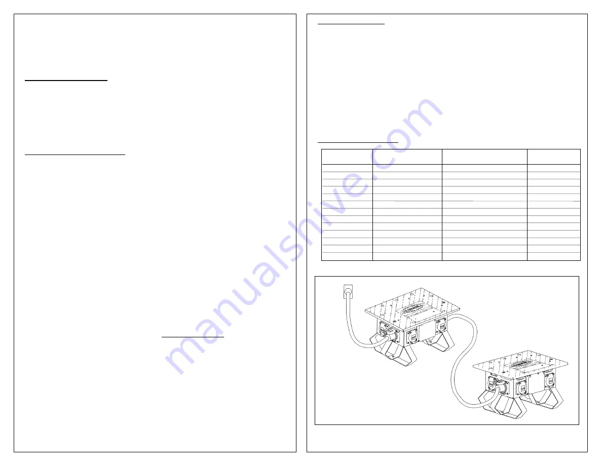
SPIDER
®
II
CAUTION:
Electrical power supply MUST
BE OFF AND DISCONNECTED before and
during any repair or maintenance. Repair
and maintenance must be performed by a
trained and competent electrician.
WARNING:
If any parts or components of
Spider II unit appear to be missing, broken or
show signs of damage, DISCONTINUE USE
IMMEDIATELY! Do not modify these devices
in any way. Replace worn or damaged
components. Failure to do so could cause
serious personal injury and/or equipment
damage.
NOTICE:
REMOVE PROTECTIVE PLASTIC FILM ON COVER AND DISCARD PRIOR TO USE.


