background image

7

INSTALLATION INSTRUCTIONS

UTB2

INSTALLATION INSTRUCTIONS

Hubbell Lighting, Inc.                                                                                                                           Doc. No. 93097040

A subsidiary of Hubbell Incorporated                                                                                                            Revision P0

701 Millennium Drive • Greenville, SC  29607          Page 7                                                          Phone (864) 678-1000

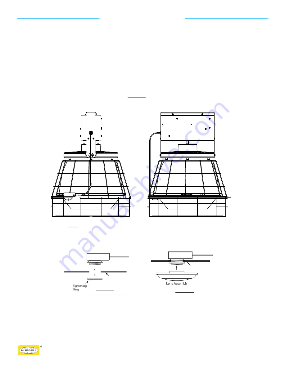
Mounting Bracket

FIGURE 7B

SENSOR INSTALLATION

FIGURE 7C

SENSOR INSTALLATION

Mounting Bracket

OCCUPANCY SENSOR INSTALLATION (If Optioned): 

NOTE: If a wireguard is supplied, the wire guard needs to be installed first (see Page 9, Fig. 7A) before installing sensor on the 

bracket.  Position the guard so the sensor bracket fits through the top two rings of the guard.


1.


Position the sensor box (without the tightening ring attached) on top of the bracket and place the threaded shaft through 

the hole in the bracket.  Fasten the tightening ring onto the threads until sensor box is secure. See Fig. 7B 

2.


Screw the sensor lens onto the threaded shaft until secure. See Fig. 7C. 


FIGURE 7A

WIRE GUARD ASSEMBLY

W/ OCCUPANCY SENSOR

OPTION SCL/SCD

SCL/SCD SENSOR BRKT & RING ASSY

MUST BE POSITIONED FOR 

CLEARANCE BETWEEN WG-16 OPENINGS

OCCUPANCY SENSOR INSTALLATION (If Optioned):

NOTE: If a wireguard is supplied, the wire guard needs to be installed first (see Page 9, Fig. 7A) before installing sensor on the
bracket. Position the guard so the sensor bracket fits through the top two rings of the guard.

1.  Position the sensor box (without the tightening ring attached) on top of the bracket and place the threaded shaft through 

the hole in the bracket. Fasten the tightening ring onto the threads until sensor box is secure. See Fig. 7B

2.  Screw the sensor lens onto the threaded shaft until secure. See Fig. 7C.

HIL_93097040_A_UTB2_INST_18

For additional information on UTB, please visit our website: 

https://www.hubbell.com/hubbellindustriallighting/en

Summary of Contents for Utilibay UTB2

Page 1: ...bserve all precautions usually followed when dealing with high voltage equipment when installing or servicing this light fixture The product must be installed in accordance with the applicable install...

Page 2: ...NG FIXTURE RECEIVING For shipping purposes the fixture will come in multiple boxes The upper assembly will be packaged separately from the reflector assembly and the lens assembly See instructions on...

Page 3: ...diary of Hubbell Incorporated Revision P0 701 Millennium Drive Greenville SC 29607 Page 3 Phone 864 678 1000 INITIAL FIXTURE ASSEMBLY 1 Align holes in Yoke to holes on side of heatsink 2 places See Fi...

Page 4: ...screws fasten the reflector to the heatsink FIGURE 3B FIGURE 3A LENS MOUNTING FIGURE 3B LENS INSTALLATION If Optioned See Figure 3B 1 Once the reflector has been mounted to the upper assembly then th...

Page 5: ...es according to the following steps 2 Thread the upper locknut with flat surface down onto the hook loop to approximately 1 8 from the top of the threads Figure 5A 3 Position the safety clasp as shown...

Page 6: ...removed from heatsink install full wire guard WG 16 onto Reflector 2 Install Reflector onto fixture heatsink using screws 4x provided LENS WIRE GUARD INSTALLATION If Optioned 1 With the screws removed...

Page 7: ...ntil sensor box is secure See Fig 7B 2 Screw the sensor lens onto the threaded shaft until secure See Fig 7C FIGURE 7A WIRE GUARD ASSEMBLY W OCCUPANCY SENSOR OPTION SCL SCD SCL SCD SENSOR BRKT RING AS...

Reviews: