background image


INSTALLATION 
MANUAL 


HUBER+SUHNER disclaims any liability resulting from incorrect installation and use, including any damages resulting from the use of tools and 

accessories other than the ones recommended in the latest revision of this installation manual. Any installation performed by unqualified personnel 

 voids the product warranty provided by HUBER+SUHNER. All due care and attention must be exercised when performing the installation of these 

products. For advice concerning the general handling of these products please contact HUBER+SUHNER. 

HUBER+SUHNER AG 

Fiber Optics 

M

ASTER

L

INE 

U

ltimate 

H

ybrid High Voltage 

4/12 (MLU HV 4/12) blunt cut at BTS side 
DOC-0000803885 Rev B 
 
November 30, 2018 
Page 1 of 12 


MASTERLINE Ultimate Hybrid High Voltage 4/12 (MLUH HV 4/12) blunt 
cut at BTS side 

TABLE OF CONTENT 

• SAFETY NOTES .......................................................................................................................................................................................... 1


• HANDLING OF THE CABLING SYSTEM .................................................................................................................................................... 1


• HANDLING OF FIBER OPTIC ASSEMBLIES ............................................................................................................................................. 1


• RRH END OF ASSEMBLY .......................................................................................................................................................................... 2


• BASE STATION END OF ASSEMBLY ........................................................................................................................................................ 9


• FIBRE OPTIC ALLOCATION ..................................................................................................................................................................... 11


• POWER CODING ...................................................................................................................................................................................... 11


• DISMANTLING ........................................................................................................................................................................................... 12


• REVISION HISTORY ................................................................................................................................................................................. 12


 SAFETY NOTES  

Installation and maintenance work on this device may only be carried out by an authorized 
electrician. National laws and regulations must be observed during installation.  
The housing and the components used must be checked for exterior damage prior to 
installation. If the cabling system is defective, it may not be used. Please contact 
HUBER+SUHNER, if there are any doubts about the condition of the cabling system. 


HANDLING OF THE CABLING SYSTEM  

To avoid any damage due to improper installation, please keep in mind below points: 


AVOID any additional stress on connector head by twisting or bending when routing or 
locating it 


AVOID installation path around any sharp objects 


AVOID uncontrolled knocking of connector head on any hard object 


AVOID any contact of connector head with any additional substance such as glue/oil/fat 
etc. unless prior authorization is given by HUBER+SUHNER AG 

See also “User handling manual for cables and cable systems” on 
www.hubersuhner.com/en/support 


HANDLING OF FIBER OPTIC ASSEMBLIES  

In  order  to  guarantee  the  performance,  fiber  optic  assemblies  need  to  be  treaded  carefully 
and with attention on the minimum bend radius and never exposed to dirt. 
See also “User handling manual for cables and cable systems” on 
www.hubersuhner.com/en/support 

Summary of Contents for MASTERLINE Ultimate Hybrid High Voltage 4/12

Page 1: ... maintenance work on this device may only be carried out by an authorized electrician National laws and regulations must be observed during installation The housing and the components used must be checked for exterior damage prior to installation If the cabling system is defective it may not be used Please contact HUBER SUHNER if there are any doubts about the condition of the cabling system HANDL...

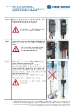
Page 2: ...hich is attached on the side of the reel The QR code leads on HUBER SUHNER s website with the latest valid revision of the installation video and installation manual Step 2 Unpack the mounting bracket It is packed together with the protection cover in a cardboard box Secure the mounting bracket with hose clamps when fitting to a pole mast or screws when fitting to a wall We recommend to use Huber ...

Page 3: ...f these products please contact HUBER SUHNER Step 4 Use a rope to pull up the cable system Check the maximum pulling force on the label attached to the hoisting grip Do not apply higher force The maximum pulling force equates to the weight of 160m cable The cable weight is specified on the data sheet Lead the rope along the left side of the MLUH connector head down onto the cable hoist and secure ...

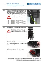
Page 4: ...LUH head into the mounting bracket Do not remove the rope from the hoisting grip before all cable clamps are mounted Step 6 Secure the MLUH connector head at the mounting bracket by tightening the two M6 screws on the bottom left and top right corner Tight the M6 screws with a torque of 2 Nm Be careful not to damage the housing by tightening the screws too tightly Step 7 Fix the cable to the mast ...

Page 5: ...r with a grounding assembly with minimum 16mm2 6 AWG cross section Consider the correct order first the grounding wire lug secondly the washer thirdly the spring washer Tighten the M8 earth screw with a torque of 5 Nm Be careful not to damage the enclosure by tightening the M8 earth screw too tightly HUBER SUHNER offers different grounding assemblies Item no 85086667 0 5m black 16mm2 2x M8 lug Ite...

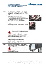
Page 6: ...R SUHNER All due care and attention must be exercised when performing the installation of these products For advice concerning the general handling of these products please contact HUBER SUHNER Pull down the cover to unlatch Flex off the cover on the bottom and move the slits above the two mounting bracket saddles Secure the protection cover with the two splints attached to the bracket Step 11 The...

Page 7: ... protection caps of the plug Twist 120 the coupling ring of the plug connector to remove protecting cap as shown Note the lock unlock symbol on the coupling ring Remove protection caps of the socket on the MLUH Twist 120 the coupling ring of the socket connector anticlockwise to remove protecting cap as shown Connect the two protection caps together for later reuse Push plug connector slightly and...

Page 8: ...position push connector to mate Mated connector snaps in and is fully strain relieved Connect the two protection caps together for later reuse Un mating Pull coupling ring to un mate Mount instantly the protection cap to avoid ingress of water or dirt All HUBER SUHNER fiber optic assemblies are 100 manufactured in an industrial environment and are governed by standards which are implemented and co...

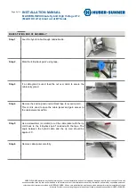
Page 9: ...stallation of these products For advice concerning the general handling of these products please contact HUBER SUHNER BASE STATION END OF ASSEMBLY Step 1 Feed the hybrid cable through cabinet cabin Step 2 Mark the strip back point using tape Step 3 If a cable gland is used feed the nut over cable to secure the cable entry gland Step 4 Remove the end cap and unwind black tape to reveal rip cord Thi...

Page 10: ...re optic cable element from the DC tails and form a loop to separate it During this process at any stage ensure the fibre optic cable is not kinked Do not over bend the cable Minimum bend radius for the fiber optic cable is 8 cm Step 8 If a cable gland at the entry point is used tighten it to secure cable and ensure IP protection Step 9 Route DC cable element to their respective termination points...

Page 11: ...e use of tools and accessories other than the ones recommended in the latest revision of this installation manual Any installation performed by unqualified personnel voids the product warranty provided by HUBER SUHNER All due care and attention must be exercised when performing the installation of these products For advice concerning the general handling of these products please contact HUBER SUHN...

Page 12: ...xercised when performing the installation of these products For advice concerning the general handling of these products please contact HUBER SUHNER DISMANTLING Dismantling is done in reverse order of installation A new suitable lace up hosting grip has to be used to lift down the cabling system Please contact HUBER SUHNER to select a proper lace up hosting grip It is recommended to place the lace...

Reviews: