Introduction
Chapter 1
OPERATION MANUAL
V2.2.0en/09.08.21//17.12
Unichiller® eo Desktop
19
1.5.2.1
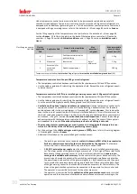
Temperature control units (with heater) with electronic low level sensor
The low level protection operates via a pressure sensor in the fluid circuit. The pump and the ther-
mal fluid provide the required pressure at the pressure sensor. Air in the system (fill level too low,
inadequately vented) prevents the pressure from reaching value specified at the pressure sensor.
Temperature control and circulation are interrupted.
Overtemperature protection
(for temperature control units with heater)
There is no longer a need for mechanical tools to set the trigger values of the overtemperature
protection. It is replaced by a software engineering tool. The threshold value for the overtempera-
ture protection can be set only if a code, randomly generated by “Pilot ONE”, is entered correctly. As
with the mechanical tool, accidental settings are thus prevented.
1.5.3
Further protective devices
Emergency strategy – interrupt the power grid connection!
To determine the type of switch or switch combination your temperature control unit is equipped
with, please refer to the wiring diagram.
→
Temperature control units with >Mains isolator<
[36]
(red/yellow or gray):
Turn the
>Mains
isolator<
[36] to the “0” position.
Temperature control units with >Mains isolator<
[36]
(red/yellow) and additional >Appliance
switch<
[37]
(gray):
Turn the
>Mains isolator<
[36] to the “0” position. Then turn the
>Appliance
switch<
[37] to the “0” position!
Temperature control units with >Mains isolator<
[36]
(gray) and >Emergency stop switch<
[70]
(red/yellow):
Press the
>Emergency stop switch<
[70]. Then turn the
>Main switch<
[36] to the
“0” position!
Temperature control units with >Mains switch<
[37]
:
Power supply via socket: Disconnect the
temperature control unit from the power supply. Then turn the
>Mains isolator<
[37] to the “0”
position! Power supply via hard wiring: Disconnect the power grid supply by means of the build-
ing’s circuit breaker. Then turn the
>Mains isolator<
[37] to the “0” position!
Temperature control units without a switch or inside a protective housing:
Connection via sock-
et: Disconnect the temperature control unit from the power supply. Connection via hard wiring:
Disconnect the power grid supply by means of the building’s circuit breaker!
1.5.3.1
Power interruption
Following a power outage (or when switching on the temperature control unit), this function can be
used to determine how the temperature control unit is supposed to respond. This response can be
determined via “Pilot ONE”.
OFF/Standby
(Default setting)
After turning the temperature control unit on, thermoregulation is started only after manual input.
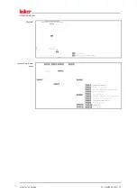
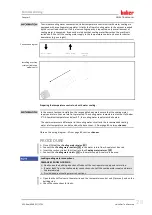
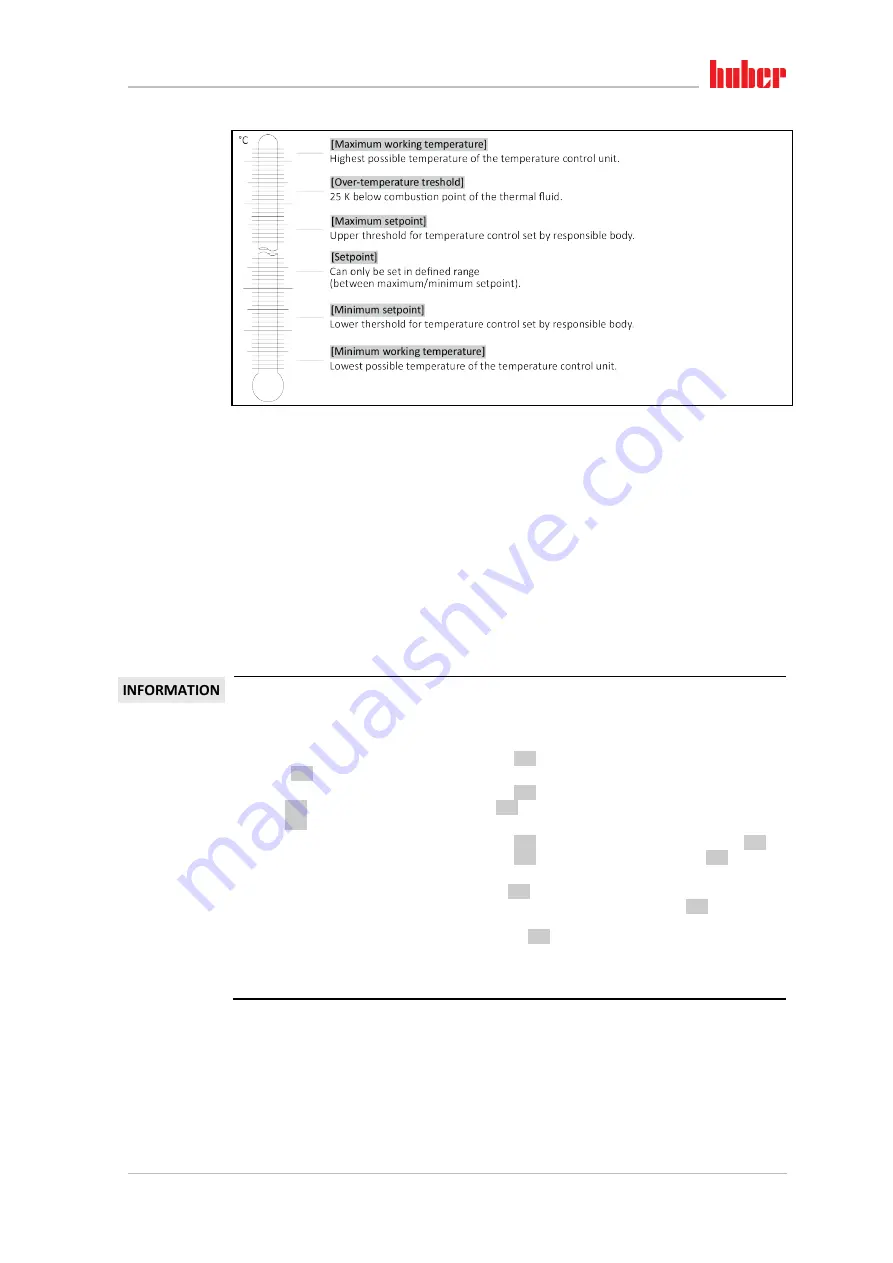
Overview of the tem-
perature thresholds

