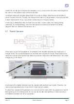
[5]
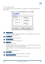
MAX. POWERLOSS
The maximum power dissipation of the power semiconductors is displayed in %. At 100%
the amplifier switches off. For short signals the maximum power dissipation can be
significantly higher than the average power dissipation. The displayed values are rated with
the heat sink temperature and therefore greater at higher temperatures.
[6]
MEAN POWERLOSS
The average power dissipation of the power semiconductors is displayed in %. It is a
measure of the long-term warming of the amplifier. At 100% the amplifier switches off. For
short signals the maximum power dissipation can be significantly higher than the average
power dissipation. The displayed values are rated with the heat sink temperature and
therefore greater at higher temperatures.
[7]
QUIT
Quits the application.
[8]
RESET INTERLOCK
Only possible if the interlock-mode latching is configured. After safety shutdown has taken
place, the interlock function must be reset manually. The amplifier can now be switched on
again (Amplifier On).
[9]
STATUS INDICATION
Green, Ready:
Signals the operational readiness of the amplifier.
Red, short-circuit_current exceeded
The short-circuit current cut-off has been activated.
Red, C exceeded
The permissible positive transistor current has been exceeded
Red, Current – exceeded
The permissible negative transistor current has been exceeded
Red, Power Loss + exceeded
The permissible operating range of the positive side of the power semiconductors has been
exceeded.
Red, Power Loss – exceeded
The permissible operating range of the negative side of the power semiconductors has
been exceeded.
Red, Temperature exceeded
The permissible temperature of the heat sink has been exceeded.
Red, Transformer temperature exceeded
The permissible temperature of the power transformer has been exceeded.
Red, Hardware Error:
An amplifier error was detected.
[10] CONNECT
Selection and activation of the device interface.
A1230-02
A1230-MultiChannel-Control Software
Page 15


