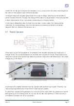
A diagram with the maximum output voltages and output currents ( UI plot ) is located in the data
sheet.
5.3 Connecting the Signal Source (Single Channel)
The A1230 has two unbalanced signal inputs with BNC connector and different input resistances
of 50 Ω and 100 kΩ. Connect a 50 Ω signal source (for instance Function Generator), the output
voltage is the same at both inputs, since the gain at 100 kΩ input v = 10 and at 50 Ω input
v = 20, and thus the voltage halving by source and input resistance compensates. In short signal
lines < 2 m it does not matter which input you choose. For longer lines the 50 Ω input is
recommended in order to avoid reflections and to ensure signal integrity. However, the source must
provide the necessary output power available to drive the 50 Ω input load (3,75 V / 50 Ω = 75 mA
3,75 V * 75 mA = 281,25 mW).
→
5.4 Connecting the Load (Single Channel)
The output of the A1230 is provided with 4 mm safety sockets at the power output. With the
cabling of your load, please also ensure sufficient contact protection; life-threatening voltages can
occur.
For safe and stable operation, the cables should be as short as possible and of similar length. The
cable cross section should not fall below 1.5 mm².
The A1230 is a fast broadband amplifier that can deliver fast pulses with very high currents. Please
remember that the wiring can contribute a significant proportion to the inductance of your load. In
critical cases you should draw a coaxial wiring into consideration.
The A1230 is stable at all complex loads. Since the output impedance of the amplifier will get
inductive at higher frequencies, this
may lead to a significant overshoot with only capacitive loads.
This behavior doe
s not indicate a possible instability of the amplifier, but is established due to an
excited series resonant circuit of output and line inductance and the connected capacity. A
damping of the resonant circuit by series resistors is recommended in this case.
5.5 Operational Startup
Connect the mains cable and switch on the mains voltage at the mains switch. The illuminated
Power button signals
Standby
and you can switch on the device.
After a short time, ready lights up and the amplifier is now ready to operate.
Select the best operating voltage for your load and connect it to one or both signal inputs of your
source(s). You can activate the respective input(s) with the illuminated 50 and 100 k buttons to
start the signal processing.
Start the software when needed and establish a data connection to the amplifier. You will receive
additional data/information concerning the operating status of your amplifier.
A1230-02
Notes on Operation
Page 19


