Switch the 100 kΩ input of the second amplifier on, so you can control the entire output signal via
the button of the selected input of the first amplifier.
In bridged mode each amplifier delivers half of the output voltage, since the second amplifier is
driven inverted to the first. Thereby, the voltage at the load is no longer based on the rest potential!
A direct measurement of e.g. a grounded oscilloscope is no longer possible.
In this case, a differential probe or similar must be used. In many cases, the missing resting
potential is not a disadvantage, since the load requires no reference potential (for example,
magnetic field coil, ultrasonic transducers, etc.)
5.7 Parallel Operation
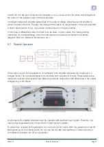
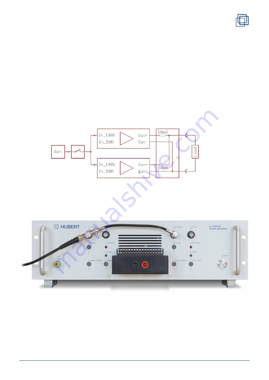
If the output current of the amplifier is not sufficient, both amplifier channels can be placed in a
bridged mode. The provided adapter box combines both outputs via 50 mΩ. These resistors are
required to prevent unnecessarily high balancing currents caused by small differences in the output
voltages (e.g. a DC offset).
At all times both amplifier channels must be operated with identical input signals. Therefore only
use one signal generator and connect both 100kΩ inputs in parallel.
To prevent an overload at the generator, do not use the 50 Ω inputs. With the generator turned off
start switching on the 100kΩ inputs. Do not use the 100 kΩ input switches or a remote control
command but instead turn off your generator.
A1230-02
Notes on Operation
Page 21


