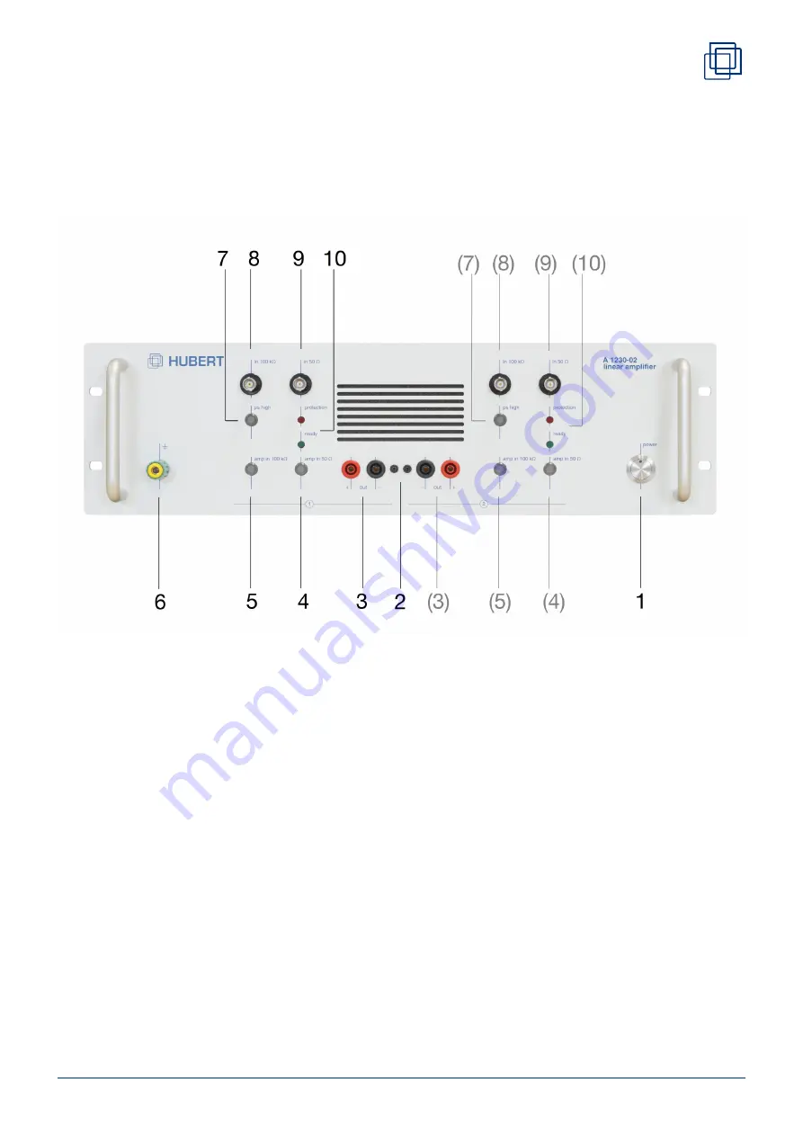
3 Operating Elements
3.1 Front Panel Elements
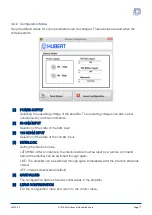
Each of the two amplifier channels has its own front panel elements (3, 4, 5, 7, 8, 9, 10).
[1]
POWER BUTTON
On / Off switch.
(Here is implemented the switchover ready to operate / standby. The standby mode is
signaled by the weakly-lit, blue LED. The power supply disconnection is implemented with
the switch on the rear side.)
[2]
SAFETY SHUTDOWN 1 / 2
2 mm jacks to connect the safety shutdowns of both channels. If connected, a safety
shutdown on one channel triggers the safety shutdown on the other channel. This
shutdown is indispensable and is provided automatically if the adapter box for parallel
operation is used. Using the safety shutdown is recommended in series operation as well.
[3]
OUT+ / OUT-
4 mm safety sockets, amplifier output
Reference potential (negative-socket) is connected to protective earth via 1 MΩ.
A1230-02
Operating Elements
Page 9


