background image


Electronic overspeed switch EGS 2 


EGS2_MANUAL-en_R3(2018-11-14)ID74563.docx 


23 


14


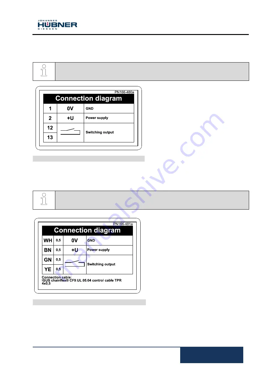
Connection diagrams 

14.1


Terminal box 


NOTES! 
The connection diagrams are displayed in each terminal box cover! 


Connection diagram PN166-480a 


14.2


Connection cable 


NOTES! 
The connection diagrams are attached to each cable! 


Connection diagram PN166-481a 


Summary of Contents for EGS 2

Page 1: ... 2018 11 14 ID74563 docx ID 74563 Operating and Assembly Instructions Electronic overspeed switch EGS 2 Straightforward monitoring of overspeed or zero speed detection Read the Operating and Assembly Instructions prior to assembly starting installation and handling Keep for future reference ...

Page 2: ... 641 7969 0 Fax 49 641 73645 E Mail info huebner giessen com www huebner giessen com The manual has been drawn up with the utmost care and attention Nevertheless we cannot exclude the possibility of errors in form and content It is strictly forbidden to reproduce this publication or parts of this publication in any form or by any means without the prior written permission of Johannes Hubner Fabrik...

Page 3: ...6 2 Rotating shafts hot surfaces 8 2 6 3 Safeguarding against restart 8 3 Technical Data 9 3 1 Type plate 9 3 2 Type code 10 3 3 Electrical and mechanical data 10 4 Overspeed monitoring 11 5 Zero speed monitoring 11 6 Transport packaging and storage 12 6 1 Safety instructions for transport 12 6 2 Goods inward inspection 12 6 3 Packaging disposal 12 6 4 Storage of packages devices 12 7 Installation...

Page 4: ...Dismantling the encoder 18 9 Faults 19 9 1 Faults table 19 10 Inspections 20 10 1 Safety instructions 20 10 2 Maintenance information 20 10 3 Inspection schedule 20 11 Disposal 20 11 1 Disposal procedure 20 12 Replacement parts 20 13 Dimension drawings 21 14 Connection diagrams 23 14 1 Terminal box 23 14 2 Connection cable 23 ...

Page 5: ...zard The warnings must be strictly heeded you must act prudently to prevent accidents personal injury and property damage WARNING Indicates a possibly dangerous situation that can result in death or serious injury if it is not avoided CAUTION Indicates a possibly dangerous situation that can result in minor injury if it is not avoided CAUTION Indicates a possibly dangerous situation that can resul...

Page 6: ...er than in conjunction with using the device without the prior written agreement of the manufacturer Any copyright infringements will be prosecuted 1 6 Guarantee terms The guarantee terms are provided in the manufacturer s terms and conditions 1 7 Customer service For technical information personnel is available that can be contacted by telephone fax or email See manufacturer s address on page 2 2...

Page 7: ...use are excluded the owner bears sole responsibility for non intended use 2 4 Improper use Do not use the device in potentially explosive areas The device must not be subjected to mechanical loads in addition to its own weight and unavoidable vibration and shock loads that arise during normal operations Examples for non permitted mechanical loads incomplete list Fastening transport or lifting tack...

Page 8: ... surfaces WARNING Danger of injury due to rotating shafts and hot surfaces Touching rotating shafts can cause serious injuries Therefore Do not reach into moving parts shafts or handle moving parts shafts during operation Close to protect from injury all access openings in flanges with the corresponding plug screw and provided you exposed rotating components with protective covers Do not open cove...

Page 9: ...ng information Englisch Deutsch Manufacturer address Hersteller Anschrift Type Overspeed switch Typ Grenzdrehzahlschalter Year of manufacture Baujahr CE mark CE Kennzeichnung Serial number S N Seriennummer S N Item ID Artikel ID Degree of protection Schutzart Supply voltage Versorgungsspannung Max speed Max Drehzahl Switching speed Schaltdrehzahl Switching voltage switching current Schaltspannung ...

Page 10: ...al strip type Phoenix ZFKDS 1 5 W 5 08 0 25 mm 1 5 mm Gerätetemperaturbereich 25 C 85 C Degree of protection acc DIN EN 60529 Sealing Rotor moment of inertia Breakaway torque IP 66 with radial shaft seal approx 100 gcm approx 3 Ncm Vibration resistance DIN EN 60068 2 6 IEC 68 2 6 10 2000 Hz 20 g 200 m s Shock resistance DIN EN 60068 2 27 IEC 68 2 27 6 ms 200 g 2000 m s Max encoder shaft load Fa ma...

Page 11: ...cally isolated switching contact changes the state as soon as the shaft leaves the zero speed Functionality At a speed of less than 0 25 rpm the zero speed monitoring is activated and the switching contacting contact is closed When the zero speed monitoring is activated the current position value is stored and monitored for possible changes in the angle of rotation As a result very slow or creepin...

Page 12: ...the carrier immediately on receipt if you determine that damage has occurred during transit take photos as proof 6 3 Packaging disposal The packaging is not taken back and must be disposed of in accordance with the respective statutory regulations and local guidelines 6 4 Storage of packages devices Keep dry Keep packages dry and free from dust protect from moisture Protect against heat Protect pa...

Page 13: ...vice the signal frequency the length of the signal cable and the place of installation please refer to Chapter 3 3 Degree of protection To fulfil degree of protection requirements the diameter of the connection cable must correspond to that of the cable gland please refer to Chapter 13 Dimension drawings Deep groove ball bearings EGS 2 overspeed switches are fitted with maintenance free greased fo...

Page 14: ...wings NOTES Fastening screws and earth cable are not included in the range of supply 2 Preparing the place of attachment Clean the motor shaft centering bolting surfaces and fastening threads check for damage Repair any damage 7 5 Mounting the encoder NOTES For a mounting example please refer to dimension drawing HM 17 M 111276 Chapter 13 Figure 1 1 9 2 10 3 12 13 4 6 8 5 14 11 15 7 ...

Page 15: ... If possible fit the intermediate flange in a manner that ensures the screwed sealing plug 14 points downwards 5 Lightly grease the encoder shaft 5 and centering 4 6 Fit the encoder 8 into both the centering 4 and coupling hub at the same time NOTES You must be able to mount the coupling without force Ream out the bores of used couplings if necessary NOTES If possible fit the device in a manner th...

Page 16: ...unting errors and should be kept as small as possible Mounting errors Cause radial forces to act on the encoder shaft Reduce the service life of the bearings and the coupling Degrade the quality of the signals harmonic content Mounting tolerances for our zero backlash torsion resistant couplings HK 5 and HKD 5 Coupling Axial offset a Angular error α Parallel offset e HK 5 1 mm 0 5 HKD 5 1 5 mm 0 5...

Page 17: ...lands 17 Fig 1 3 Feed the cable into the terminal box trough the cable glands NOTES The signal cable shielding has to be connected directly to the housing via the EMC cable gland To achieve an effective shielding the cable shield must also be connected in the electrical cabinet 4 Tighten the cable gland using a spanner NOTES Prior to delivery cable glands and blanking plugs are tightened finger ti...

Page 18: ...e terminal box cover that no cable becomes jammed 8 Dismantling 8 1 Safety instructions Personnel Dismantling must be carried out by skilled technical staff only WARNING Observe the safety instructions contained in Chapter 2 when dismantling the device NOTES Do not use a hammer or similar tool when dismantling the device due to the risk of damage occurring to the bearings or coupling 8 2 Dismantli...

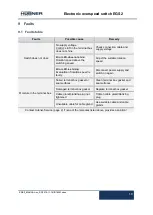
Page 19: ...t the suitable rotation speed Error LED is shining Evaluation of rotation speed is faulty Disconnect power supply and switch on again Moisture in the terminal box Soiled terminal box gasket or seal surfaces Clean terminal box gasket and seal surfaces Damaged terminal box gasket Replace terminal box gasket Cable gland blanking plug not tightened Tighten cable gland blanking plug Unsuitable cable fo...

Page 20: ...ghtened Ensure cable connections and connection terminals are securely seated Following approx 16 000 20 000 hours of operation higher levels of continuous load Check deep groove ball bearings are running smoothly and listen for running noises 11 Disposal 11 1 Disposal procedure The manufacturer is not obliged to take back the device The device is classed as electronic equipment observe local coun...

Page 21: ...Electronic overspeed switch EGS 2 EGS2_MANUAL en_R3 2018 11 14 ID74563 docx 21 13 Dimension drawings ...

Page 22: ...Electronic overspeed switch EGS 2 22 EGS2_MANUAL en_R3 2018 11 14 ID74563 docx ...

Page 23: ...D74563 docx 23 14 Connection diagrams 14 1 Terminal box NOTES The connection diagrams are displayed in each terminal box cover Connection diagram PN166 480a 14 2 Connection cable NOTES The connection diagrams are attached to each cable Connection diagram PN166 481a ...

Reviews: