background image

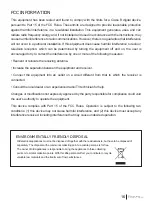
FCC INFORMATION

This equipment has been tested and found to comply with the limits for a Class B digital device, 
pursuant to Part 15 of the FCC Rules. These limits are designed to provide reasonable protection 
against harmful interference in a residential installation. This equipment generates, uses, and can 
radiate radio frequency energy and, if not installed and used in accordance with the instructions, may 
cause harmful interference to radio communications. However, there is no guarantee that interference 
will not occur in a particular installation. If this equipment does cause harmful interference to radio or 
television  reception,  which  can  be  determined  by  turning  the  equipment  off  and  on,  the  user  is 
encouraged to try to correct the interference by one or more of the following measures:

• Reorient or relocate the receiving antenna.

• Increase the separation between the equipment and receiver. 

•  Connect  the  equipment  into  an  outlet  on  a  circuit  different  from  that  to  which  the  receiver  is 
connected. 

• Consult the local dealer or an experienced radio/TV technician for help.

Changes or modifications not expressly approved by the party responsible for compliance could void 
the user’s authority to operate the equipment.

This  device  complies  with  Part  15  of  the  FCC  Rules.  Operation  is  subject  to  the  following  two 
conditions: (1) this device may not cause harmful interference, and (2) this device must accept any 
interference received, including interference that may cause undesired operation.

ENVIRONMENTALLY FRIENDLY DISPOSAL

Old electrical appliances must not be disposed of together with the residual waste, but have to be disposed of 
separately. The disposal at the communal collecting point via private persons is for free. 
The owner of old appliances is responsible to bring the appliances to thise collecting 
points or to similar collection points. With this little personal effort, you contribute to recycle 
valuable raw materials and the treatment of toxic substances.

16

©

2016  Hubsan

哈博森科技 版权所有

Summary of Contents for H502C

Page 1: ...M DISARM MOTORS SEE PAGE 06 RTH FUNCTION SEE PAGE 09 COMPASS CALIBRATION SEE PAGE 12 TRANSMITTER CALIBRATION SEE PAGE 13 Ages 14 READ THE INSTRUCTION MANUAL CAREFULLY PLEASE VISIT WWW HUBSAN TO UPGRAD...

Page 2: ......

Page 3: ...oid injuries from accidentally powering on the motors Always take great caution to protect yourself when near the propellers The flight system will start after powering on regardless of the transmitte...

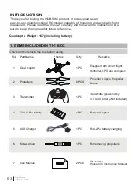
Page 4: ...i Po battery 1PC For quad copter Transmitter powered by 4 X AAA battery Not included 3 Transmitter 1PC Thank you for buying the HUBSAN product It is designed as an easy to use multi functional RC mode...

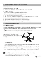
Page 5: ...link simultaneously every 1 5 seconds 2 Compass Calibration 1 Horizontal calibration 4 LED indicators blink circularly 2 Vertical calibration 4 LED indicators blink alternately 3 GPS Flight 4 LED indi...

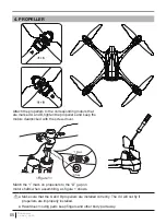
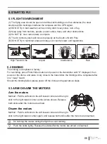
Page 6: ...llers to the corresponding motors that are marked A and B tighten the propellers and keep the motors deadlocked with the screw driver Hazardous moving parts keep fingers and other body part away Make...

Page 7: ...left lowest corner and the right stick to the right lowest corner as the picture shows Release both sticks after the motors are armed Disarm the motors Method Pull the left stick to the left lowest c...

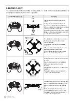
Page 8: ...e stick right and the X4 will rotate clockwise When the stick is in the center the X4 will keep the current direction and not rotate Pushing harder will cause the X4 to rotate faster in the correspond...

Page 9: ...ks ONLY when the GPS signal has no less than 6 satellites 2 Home Point is recorded when armed the motors with no less than 6 GPS satellites 3 You should be in an open place to search for the GPS satel...

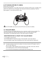
Page 10: ...strong electronic interference To ensure that the X4 can return safely to its home point when GPS signal is lost fly the X4 in safe flight area If the quantity of GPS satellites drops below six for mo...

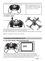
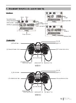
Page 11: ...Stick 2Throttle Rudder Stick MODE 1 MODE 2 1 Photo Video 4 Power Switch 5 Elevator Trim 6 Aileron Trim 3 Rudder Trim Motor LED Switch 2 Elevator Rudder Stick 9 Throttle Aileron Stick 7 LCD 8 RTH Inter...

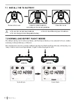
Page 12: ...r stick 0 5 second to shift between Normal Mode and Expert Mode indicated by one beep When it enters into Expert Mode Expert will be displayed on LCD Normal Mode Expert Mode Do not mix old and new bat...

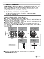
Page 13: ...ntil the Set Compass 2 on screen disappears 4 Calibration done Do not calibrate the compass in a strong magnetic field Do not carry ferromagnetic materials with you while calibrating the compass such...

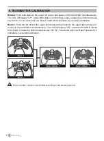
Page 14: ...cles three times release the sticks and press any trim for 1 5 seconds until one Beep heard which indicates a successful calibration Mode 1 Push the left stick to the upper left corner and right stick...

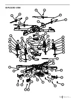
Page 15: ...29 29 29 29 17 16 5 16 6 20 26 26 26 26 26 26 26 26 20 21 28 28 28 28 27 27 27 27 21 27 27 27 27 8 8 8 8 9 19 14 12 12 11 15 13 22 25 30 18 3 3 3 3 4 1 14 13 12 11 15 28 28 28 28 7 10 2 23 19 18 14 1...

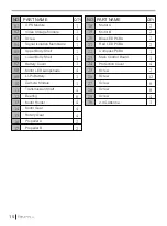
Page 16: ...on Membrane Upper Body Shell Lower Body Shell Battery Cover Motor LED Lampshade Li Po Battery Camera Module Transmission Shaft Bearing Motor Holder Motor Gear Rotary Gear Propeller A Propeller B 1 1 4...

Page 17: ...t and receiver Connect the equipment into an outlet on a circuit different from that to which the receiver is connected Consult the local dealer or an experienced radio TV technician for help Changes...

Page 18: ...17 2016 Hubsan...

Page 19: ......

Page 20: ...User manual is subject to change without prior notice due to unforseen product upgrades Download the latest user manual from WWW HUBSAN COM VERSION 1 0 EN...

Reviews: