background image

06

©

2016  Hubsan

5.1 FLIGHT ENVIRONMENT 

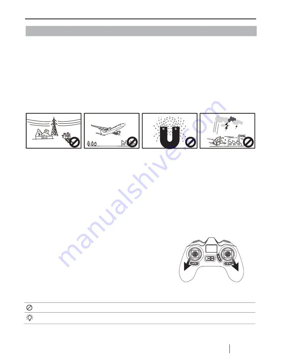
(1) The flying area should be open and without tall buildings or other obstacles; the steel       

structure within buildings interferes the compass and the GPS signal.
(2) DO NOT fly in bad weather such as strong wind, heavy snow, rain or fog.
(3) Keep away from barriers, people, power cables, trees, and other obstructions. 
(4) Do NOT fly  near radio towers or airports.
(5) The X4 control system will not work properly at the South or North Pole
(6) DO NOT fly in restricted areas and obey your country's laws and regulations.

5. START TO FLY

5.3 ARM/ DISARM THE MOTORS


Arm the motors

Method : Pull the left stick to the left lowest corner and the right 
stick to the right lowest corner as the picture shows. Release 
both sticks after the motors are armed.

Disarm the motors

Method : Pull the left stick to the left lowest corner and the right 
stick to the right lowest corner again, and release both sticks after the motors are disarmed. 


Do not stop the motors during the flight to avoid crashing.


Push the sticks lightly. Release the sticks after the motors are armed or disarmed.


High Tension Line

Rain

Interference

Airport

5.2 BINDING

The binding is completed in factory. 
For re-binding, press Photo/Video button and power on the transmitter simultaneously until “H” 
displayed, then power on the drone, and place it very close to the transmitter, the binding will be 
completed after one “ beep” heard. 
Should the binding failed, please power off the drone and repeat above steps.

Summary of Contents for X4 DESIRE H502E

Page 1: ...DISARM MOTORS SEE PAGE 06 RTH FUNCTION SEE PAGE 09 COMPASS CALIBRATION SEE PAGE 12 TRANSMITTER CALIBRATION SEE PAGE 13 Ages 14 READ THE INSTRUCTION MANUAL CAREFULLY PLEASE VISIT WWW HUBSAN TO UPGRADE THE HUBSAN X4 DESIRE ...

Page 2: ...ON BEFORE FLY Do not calibrate the compass in a strong magnetic field Do not carry ferromagnetic materials with you while calibrating the compass such as keys cell phones etc Compass calibration is required after the binding as instructed on the transmitter START DONE Rotate the quadcopter vertically until Set Compass 2 disappears Rotate the quadcopter horizontally until Set Compass 2 displays ...

Page 3: ... to avoid injuries from accidentally powering on the motors Always take great caution to protect yourself when near the propellers The flight system will start after powering on regardless of the transmitter signal The high speed propellers are very dangerous Power off the X4 after every flight or the propellers may still rotate and cause injury Hubsan X4 Desire Please read the instruction manual ...

Page 4: ...ry 1PC For quad copter Transmitter powered by 4 X AAA battery Not included 3 Transmitter 1PC Thank you for buying the HUBSAN product It is designed as an easy to use multi functional RC model capable of hovering and acrobatic flight maneuvers Please read the manual carefully and follow all the instructions Be sure to keep the manual for future reference 7 2PCS Disclaimer Hubsan X4 Instruction Manua...

Page 5: ...s red 1 Power on 4 LED indicators blink simultaneously every 1 5 seconds 2 Compass Calibration 1 Horizontal calibration 4 LED indicators blink circularly 2 Vertical calibration 4 LED indicators blink alternately 3 GPS Flight 4 LED indicators remain lighted 4 GPS Return 2 front LED remain lighted and 2 back LED blink twice every second 5 Photo 2 front LED remain lighted 2 back LED blink once 6 Vide...

Page 6: ...g parts keep fingers and other body part away Make sure that the A and B propellers are installed correctly The X4 will not fly if propellers are improperly installed Match the I mark on propellers to the D gap on motor shafts when assembling as figure 1 shows I Mark D Gap Figure 1 Black screw Silver screw Tighten the A propeller with black screw Tighten the B propeller with sliver screw A B ...

Page 7: ...owest corner and the right stick to the right lowest corner as the picture shows Release both sticks after the motors are armed Disarm the motors Method Pull the left stick to the left lowest corner and the right stick to the right lowest corner again and release both sticks after the motors are disarmed Do not stop the motors during the flight to avoid crashing Push the sticks lightly Release the...

Page 8: ...he stick right and the X4 will rotate clockwise When the stick is in the center the X4 will keep the current direction and not rotate Pushing harder will cause the X4 to rotate faster in the corresponding directions Right rotation Left rotation Forward Backward Right Left The Elevator stick controls the X4 forward and backward Push the stick up and the X4 will fly forward Pull the stick down and t...

Page 9: ...rks ONLY when the GPS signal has no less than 6 satellites 2 Home Point is recorded when armed the motors with no less than 6 GPS satellites 3 You should be in an open place to search for the GPS satellites it ll take 3 mins to finish the searching and the GPS signal strength depends on the flying environment 6 ADVANCED PERFORMANCE SETUP Set Set RTH only available when there are no less than 6 GPS...

Page 10: ... strong electronic interference To ensure that the X4 can return safely to its home point when GPS signal is lost fly the X4 in safe flight area If the quantity of GPS satellites drops below six for more than 20 seconds while the X4 is returning home the X4 will descend automatically The X4 will not avoid obstacles automatically while in failsafe mode The RTH MODE only works when the GPS with no l...

Page 11: ...ottle Rudder Stick MODE 1 MODE 2 1 Photo Video 4 Power Switch 5 Elevator Trim 6 Aileron Trim 3 Rudder Trim Motor LED Switch 2 Elevator Rudder Stick 9 Throttle Aileron Stick 7 LCD 8 RTH Interface Tansmitter battery voltage display GPS satellites GPS Mark Quad copter battery voltage display Head orientation Video Photo Expert Normal Distance Mark Distance Height Mark Height ...

Page 12: ...or stick 0 5 second to shift between Normal Mode and Expert Mode indicated by one beep When it enters into Expert Mode Expert will be displayed on LCD Normal Mode Expert Mode Do not mix old and new batteries Do not mix different types of batteries Do not charge non rechargeable battery 7 1 INSTALL THE TX BATTERY Close the cover Remove the cover Install 4 x AAA batteries according to the correct po...

Page 13: ...he right stick left to right quickly until the transmitter displays Set Compass 1 2 Rotate the X4 horizontally clock wise until the LCD screen displays Set Compass 2 3 Put the X4 nose down and rotate it vertically clock wise until the Set Compass 2 on screen disappears and 4 LED indicators remain lighted 4 Calibration done Do not calibrate the compass in a strong magnetic field Do not carry ferrom...

Page 14: ...for three times then release both sticks press any trim for 1 5 seconds until one Beep heard which indicates a successful calibration Mode 1 Push the left stick to the upper left corner and right stick to the upper right corner and power on the transmitter simultaneously The LCD will display H rotate both sticks in circles for three times then release both sticks press any trim for 1 5 seconds unt...

Page 15: ...D VIEW 25 27 28 3 15 30 30 9 24 25 26 33 28 28 10 24 26 28 16 2 8 11 23 10 24 25 26 27 28 28 9 24 25 26 33 28 28 4 5 13 14 20 20 21 21 22 31 34 31 34 32 12 12 6 6 17 18 19 19 19 19 29 29 29 29 29 29 29 29 29 29 29 30 30 30 1 ...

Page 16: ...tor B Li Po Battery 2 4G Attenna Upper Body Shell GPS Shielding Case Battery Cover Lens Holder 1 4 2 2 1 1 4 4 4 2 8 12 12 2 2 2 2 18 19 20 21 22 23 24 25 26 27 28 29 30 31 32 33 34 NO PART NAME QTY Eye Lampshade Rubber Feet Propeller A Propeller B Signal Isolation Membrane Battery Compartment Motor Holder Rotary Gear Motor Gear Motor Shaft A Bearing Screw PA1 4 7 Screw PA1 4 5 Screw PM1 4 5 Screw...

Page 17: ... A B H502 05 Motor A H502 06 Motor B H502 07 Motor Holder H502 08 Shaft Sleeve H502 20 Protection Cover H502 10 Motor Gear B H502 11 Motor Shaft H502 12 LED Kit H502 13 2 4G RX H502E 06 Camera Module 720P H502 14 GPS Module H501S 13 Compass Module H502E 05 Crash Pack H502 21 Battery Pack H502 16 Battery H502E 07 TX H502 18 USB Charger H502 19 Screwdriver 16 2016 Hubsan ...

Page 18: ...eiver Connect the equipment into an outlet on a circuit different from that to which the receiver is connected Consult the local dealer or an experienced radio TV technician for help Changes or modifications not expressly approved by the party responsible for compliance could void the user s authority to operate the equipment This device complies with Part 15 of the FCC Rules Operation is subject ...

Page 19: ......

Page 20: ...User manual is subject to change without prior notice due to unforseen product upgrades Download the latest user manual from WWW HUBSAN COM VERSION 1 2 EN ...

Reviews: