background image


© 

2011 by Huchez Treuils S.A.S.


Translation of the original instructions manual

10

UK 

Reproduction prohibited


8.4 – Power supply 

 
Before  undertaking  any  operation  on  the  electrical  unit,  check  that  the  power  supply  to  the 
machine is off. 
A disconnecting switch must be placed no more than 10 metres from the place of use. 
 
Very  important:  the  winch  will  only  provide  full  power  if  the  motor  is  supplied  via  a  cable 
section which is perfectly suited to this use.  
Provide protection for individuals in front of the electrical unit. 
 

8.4.1 – Electrical connections 

 
The  power  supply  cable,  the  protective  fuses  and  the  main  disconnecting  switch  (see 
wiring diagram) must be provided by the customer. 
Check that the supply network complies with the machine. 
Check  the  type  of  current;  there  must  not  be  more  than  about  5%  deviation  from  the 
rated voltage 
Neutralise electrical sources 
Check that the main power supply switch on the winch is in the off position. 
Do  not  connect  the  power  supply  cable  to  the  machine  using  connection  terminals  (split 
fittings etc.) 
Do not use a cable with a smaller section to supply power to the machine. Power supply 
via a generator is possible:  

-


Minimum power of 3.75 kVA according to the models 250 and 400 kg. 

-


Minimum power of 5,5 kVA according to the models 1000 kg. 

Never  "shunt"  the  disconnecting  switches,  electrical  switches,  prevention  or  limitation 
equipment. 
Never block, adjust or remove switches or end stops in order to go beyond the levels that 
they allow. 
A  disconnecting  switch  must  be  placed  no  more  than  10  metres  from  the  place  of  use. 
Recommended rope section: 
 

VOLTAGE 

TENSION 

TYPE 

Length of supply rope 

10 m 

30 m 

230 V single 

phase 

230 V mono 

2 + T 

2.5 mm² 

4 mm² 

230 V three 

phase 

230 V tri 

3 + T 

4 mm² 

4 mm² 

400 V three 

phase 

400 V tri 

3 + T 

2.5 mm² 

2.5 mm² 


8.4.2 – Connection 


Connect the power supply using the single phase or three phase male connector supplied 
using about 0.5 m of power supply cable. 
Check that the winch works (direction of rotation) 


Do not change the direction labels in the control unit or in the winch's internal wiring. 

8.5 – Work rope 


Important: the direction of rotation of the drum depends on the way in which the machine is 
connected (order of the three-phase current phases) 
Reminder: check the maximum capacity of the winch 


Very important: 


The safety regulations require that 2 to 3 coils of rope always be left on the drum. 

To  comply  with  the  legislation,  the  rope  diameter  must  not  exceed  the  recommended 
diameter. 

If the rope and the hook used were not supplied with the machine by the manufacturer, check 
that they guarantee a level of safety corresponding to table § 6.5. 

When the winch is supplied with the rope wound on, it has not been tautened during assembly.

Summary of Contents for PRIMO INOX BT 1000

Page 1: ... 2011 by Huchez Treuils S A S Stainless steel electric winch Stainless steel electric winches PRIMOINOXfrom250to1000kg Instruction manual ______________________ UK 245 120 18 1 ...

Page 2: ...he reliability and service life of the winch The instruction manual must always be available in the place where the winch is being used In addition to the set up instructions and regulations concerning the prevention of accidents the work safety and professional regulations in force in each country must also be respected This equipment is governed by European regulations and more specifically Dire...

Page 3: ...truction manual Failure to comply with these instructions increases the level of risk Only the people designated by the company are authorised to operate the winch Before using the winch for the first time familiarise yourself with its conditions of use To this end read the present instruction manual carefully and in its entirety and perform all the operations described herein one after the other ...

Page 4: ... these parts if these operations are performed exclusively by their personnel or a representative approved by the manufacturer The parts replaced become the property of the seller and must be returned to them at their own expense In the case of components with a particular relative importance not manufactured by the seller themselves and which bear the brand of a specialist manufacturer the warran...

Page 5: ...the frequency If the operations involve the replacement of certain components of the machine the references of these components are indicated The English version of the maintenance booklet for our lifting winches can be downloaded from our website www huchez fr uk under the heading After sales services A copy is however proposed in the annexes of this manual The inspections must be carried out in ...

Page 6: ...the original instructions manual 6UK Reproduction prohibited Models PRIMO INOX BT 250 400 PRIMO INOX BT 1000 A mm 476 580 B mm 528 615 C mm 244 326 ØD mm 85 140 E mm 250 260 F mm 214 280 ØG mm 9 17 J mm 10 30 M mm 117 170 N mm 113 171 T mm 257 280 ...

Page 7: ...pe kg 40 40 40 40 90 90 Important the diameter of the rope indicated above corresponds to the rope recommended in the FEM 1 Bm ISO M3 classification It also corresponds to the capacity on the last layer Important it is obligatory to check that the rope resistance coefficient complies with the load lifted FEM 1 Bm ISO M3 6 4 Options These winches can be supplied optionally with Rope press roller Gr...

Page 8: ... rated capacity t operating time with payload or partial load dead load total operating time Y dead load maximum capacity t Δ operating time with dead load only total operating time FEM classification Usage rate PRIMO INOX 250 400 1000 Average operating time per day in hours 15 30 1 h 2 h Light 1Dm 1Dm 1Cm 1Bm Medium 1Dm 1Cm 1Bm 1Am Heavy 1Cm 1Bm 1Am 2m Very heavy 1Bm 1Am 2m 3m 7 Handling Storage ...

Page 9: ...direction of the arrows indicated on the control unit Check that the brake works with a nominal load attached lift the load and lower it again or in the case of pulling pull this load Check that the limit switch works The winch has been subjected to dynamic and static tests in the factory cf Test record 8 2 Place of installation These winches must be installed and bolted to a flat solid and secure...

Page 10: ...ording to the models 1000 kg Never shunt the disconnecting switches electrical switches prevention or limitation equipment Never block adjust or remove switches or end stops in order to go beyond the levels that they allow A disconnecting switch must be placed no more than 10 metres from the place of use Recommended rope section VOLTAGE TENSION TYPE Length of supply rope 10 m 30 m 230 V single pha...

Page 11: ...ipment which meets the same specifications as the original rope This replacement must be recorded in the maintenance booklet IMPORTANT even if the rope was supplied with the winch it was not tautened during assembly The user must tauten it using a minimum force of 1 of its breaking load Measuring the rope diameter using sleeve callipers Correct measurement Incorrect measurement Handling steel rope...

Page 12: ...on Take a mallet or a block of wood and knock the turns against one another not too hard to prevent the strands from overlapping one another but tightly enough to prevent the rope from moving on the drum If the first layer is wound too loose the next layer will form a space in the first layer that will result in an open area If the first layer is too tight the subsequent layers will not have enoug...

Page 13: ... of cable winding according to the motor connection Right hand rope Wind from the left towards the right Right hand rope Wind from the right towards the left Left hand rope Wind from the right towards the left Left hand rope Wind from the left towards the right Reeving principle Smooth drum 1 5 max Grooved drum 2 max D 20 x L ...

Page 14: ... grease The reducer is lubricated using RENOLIT CXI 2 fabricant FUCHS Very important In the event of a change in the type of grease contact our after sales service Winches Remove the bulk of the dirt from the winch Always store the winch in a dry place Ropes The ropes must be cleaned and greased regularly using a special grease which penetrates to the rope core Only use appropriate and harmless cl...

Page 15: ...e friction surface at the bottom of the motor On stopping the motor the magnetic field disappears The central spring closes the brake again by bringing the conical panel back into contact with the motor s rear flange 10 Taking out of use If the equipment is in a state of disrepair likely to give rise to risks the user is obliged to ensure that this equipment is eliminated i e prevented from operat...

Page 16: ... missing Check the power supply Circuit breaker activated instantly Short circuit in the power supply cables Eliminate the short circuit Short circuit in the motor Have the fault corrected in an approved workshop Power supply cables incorrectly connected Correct the connection Motor earth fault Have the fault corrected in an approved workshop Speed greatly reduced when loaded Voltage drop Increase...

Page 17: ... 2011 by Huchez Treuils S A S Translation of the original instructions manual17UK Reproduction prohibited 13 Declaration of EC conformity ...

Page 18: ...OX 400 kg p 23 PRIMO INOX 1000 kg p 25 C Electrical diagrams Important the following diagrams correspond to a standard installation of our standard models If the winch is adapted to a specific use a specific electrical diagram is required do not hesitate to contact us to obtain this PRIMO INOX in low voltage control single phase p 32 PRIMO INOX in low voltage control three phase p 34 D Limit switc...

Page 19: ...nd 1000 kg PRIMO INOX 250 400 PRIMO INOX 1000 No Qty Part no Qty Part no Description 1 1 24696 1 24697 Limit switch 2 2 13124 2 13694 Limit switch fixing screw 3 4 13208 Washer 4 2 13351 Brake nut 5 1 24694 1 24694 Oldham disk 6 1 24690 1 24762 Limit switch end 7 4 13614I 3 13058 Support fixing screw 8 1 24673 1 24755 Limit switch support 1000 250 400 ...

Page 20: ...NLESS STEEL 8 3 13688 13688 13688 13688 Screw TBHC M8x16 9 1 23777 23777 23777 23777 Neoprene joint Ø4 10 1 24650 24650 24650 24650 Welded reducing flange 11 1 24654 24654 24654 24654 Welded outer flange 12 1 24657 24657 24657 24657 Transmission casing 13 1 24658 24658 24658 24658 Sub unit drum 14 3 24664 24664 24664 24664 Tie Rod 15 1 24665 24665 24665 24665 Drum bearing housing 16 1 24666 24666 ...

Page 21: ...iginal instructions manual21UK Reproduction prohibited PRIMO INOX 1000 kg Part references THE SERIAL NUMBERMUSTBESPECIFIED FOR ALLSPARE PARTORDERS PRIMO INOX 1001 BT No Qty Part no Description No Qty Part no Description Not communicated Not communicated ...

Page 22: ... 2011 by Huchez Treuils S A S Translation of the original instructions manual22UK Reproduction prohibited C ELECTRICAL DIAGRAMS Wiring diagram for the single phase low voltage control PRIMO INOX ...

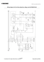
Page 23: ... 2011 by Huchez Treuils S A S Translation of the original instructions manual23UK Reproduction prohibited Wiring diagram for the three phase low voltage control PRIMO INOX ...

Page 24: ...ore doing anything turn off the main power supply to the winch To set the cams properly loosen the central screw of the group of cams Then set the trigger point for each cam using their adjustment screws The screws are numbered to indicate the cams in increasing order from the bottom of the group to the top Retighten the central screw ...

Page 25: ... the original instructions manual25UK Reproduction prohibited E MAINTENANCE BOOKLET The English version of the maintenance booklet for our lifting winches can be downloaded from our website www huchez fr uk under the heading After sales services ...

Page 26: ... 2011 by Huchez Treuils S A S Translation of the original instructions manual26UK Reproduction prohibited ...

Reviews: