212
Series Tooling Alcoa Fastening Systems
29
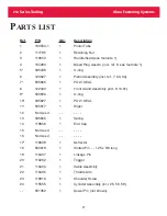
No.
P/N
Qty
Description
50
116585
1
Muffler End Cap
51
504127
3
Screw-Button Hd.- -10-32 x 5/8 long
52
115558
1
Throttle Valve Assem. (incI. 28, 53, 54)
53*
504407
1
O-ring
54*
504408
2
O-ring
55
120588
1
Anvil Stop
56
123149
1
Damper
57
Not Used
- -
- - - -
58
115504
1
Bushing Upper
59
115503
1
Bushing Lower
60
115436
1
Air Hose
61
121377
1
Damper Tube
62
122432
1
Gland Cap
63*
506654
1
Washer
64*
506653
1
Retaining Ring
(1) For replacement of machined handle/head only, Handle/head, 119653 and Bleed Plug
Assembly, 104293 are required.
(2) When Bleed Plug Assem. 104293, has been removed and reinstalled in tool 5 times,
NYLOK locking element in plug becomes worn out, therefore, worn out bleed plug must
be replaced with new plug to prevent hydraulic fluid loss.
Rev 6-20-94 includes:
(29)(32)(33)(34)(35)
Rev 9-1 -94 includes:
(6)(7)(42)(43)(56)(63)(64)
P
ARTS LIST
(
CONT
.)
Summary of Contents for ALCOA 212
Page 1: ...11 09 2009 HK838 INSTRUCTION MANUAL 212 PNEUDRAULIC INSTALLATION TOOL...
Page 2: ......
Page 4: ...This page is intentionally blank...
Page 8: ...212 Series Tooling Alcoa Fastening Systems 6 Fig 1 Outline Drawing...
Page 23: ...212 Series Tooling Alcoa Fastening Systems 21 Fig 5 Handle Assembly...
Page 25: ...212 Series Tooling Alcoa Fastening Systems 23 Fig 10 Piston and Gland Removal...
Page 26: ...212 Series Tooling Alcoa Fastening Systems 24 Fig 11 Piston and Gland Insertion assembly...
Page 27: ...212 Series Tooling Alcoa Fastening Systems 25 Fig 12 Gland Assembly...
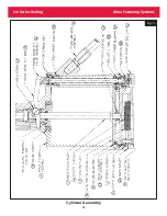
Page 28: ...212 Series Tooling Alcoa Fastening Systems 26 Fig 13 Cylinder Assembly...


