6
HS24LH
Tooling Alcoa Fastening Systems
P
REPARATION FOR USE
(F
OR
5/8” - 16
MM
)
1. Set the Huck POWERIG
PULL
pressure to 7,000 psi.
and
RETURN
pressure to 6,000 psi.. (Refer to
POWERIG instruction manual for setting pressures.)
2. Connect the Controller/Manifold to the POWERIG
per Controller/Manifold instruction manual.
3. Connect the tool's electrical, air and hydraulic lines to
the Controller/Manifold.
4. Select any tool and fastener in the controller as the
HS24 will not appear in the controller’s menu.
5. Change the controller to the following baseline
settings and adjust as necessary.
Controller Swage Pressure:
6,800 psi.
Controller Snub Pressure:
2,000 psi.
6. Turn on the POWERIG and run the warm-up cycle on
the Controller one or two times to remove all air from
the tool and hoses.
7. The HS24LH tool comes with a 5/8” - 16mm anvil
and thimble installed on tool.
(If these have been
removed from the tool re-install at this time)
8. Test the tool by installing a fastener in washers at the
proper grip. Adjust POWERIG and Controller
settings as necessary to obtain a properly swaged
fastener.
!
WARNING - Be sure to connect tool hoses to
hydraulic unit BEFORE connecting tool
electrical switch cord to unit. Hoses and
switch must be connected in this order and
disconnected in the reverse order to prevent
possible severe personal injury.
!
WARNING - Proper PULL and RETURN
pressures are important for proper function
of Installation Tools. Severe personal injury
or damage to equipment may occur without
correct pressures. Huck Pressure Gauge
P/N T-10280 (old style) or the new T124833
is now available for checking these
pressures using instructions furnished with
the gauge and in applicable POWERIG®
Hydraulic Unit instruction manuals. See
Specifications.
P
RINCIPLE OF OPERATION
When the Trigger is depressed and held down,
the automatic installation cycle starts. The Air
Motor is activated and rotates the Thimble
(clockwise), engaging onto the exposed thread of
the bolt. When the Thimble has engaged a
predetermined length of the thread (detected by
the Limit Switch Rod), the Air Motor stops and the
Powerig is activated, supplying hydraulic fluid
(Pull Pressure) to the rear of the Tool Piston
which moves forward to begin the Collar swaging
process. The Swaging Anvil then moves down
over the Collar. When a predetermined hydraulic
pressure (Pull Pressure) is reached, hydraulic
fluid (Return Pressure) is directed to the front of
the Piston, moving it rearward. The Swaging
Anvil then disengages from the Collar. The Air
Motor is then activated and rotates the Thimble
(counter-clockwise) to disengage the Tool from
the bolt thread. The Air Motor then stops and the
system is ready to install the next fastener.
Summary of Contents for HS24LH
Page 1: ...Form HK 1024 04 22 2004 INSTRUCTION MANUAL HS24LH HYDRAULIC INSTALLATION TOOL ...
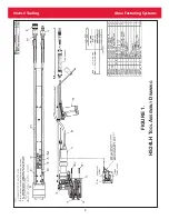
Page 9: ...9 HS24LH Tooling Alcoa Fastening Systems FIGURE 1 HS24LH T OOL A SSEMBLY D RAWING ...
Page 10: ...10 HS24LH Tooling Alcoa Fastening Systems FIGURE 2 126601 S WITCH A SSEMBLY D RAWING ...
Page 11: ...11 HS24LH Tooling Alcoa Fastening Systems FIGURE 3 126570 C YLINDER A SSEMBLY D RAWING ...
Page 12: ...12 HS24LH Tooling Alcoa Fastening Systems FIGURE 4 126571 P ISTON A SSEMBLY D RAWING ...
Page 13: ...13 HS24LH Tooling Alcoa Fastening Systems FIGURE 5 126572 E ND C AP A SSEMBLY D RAWING ...
Page 14: ...14 HS24LH Tooling Alcoa Fastening Systems FIGURE 6 126602 H YDRAULIC A SSEMBLY D RAWING ...
Page 15: ...15 HS24LH Tooling Alcoa Fastening Systems FIGURE 7 126603 H ANDLE W IRING A SSEMBLY D RAWING ...
Page 16: ...16 HS24LH Tooling Alcoa Fastening Systems FIGURE 8 126604 D RIVE A SSEMBLY D RAWING ...
Page 18: ...18 HS24LH Tooling Alcoa Fastening Systems SERVICE NOTES ...


