7
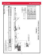
HS24LH
Tooling Alcoa Fastening Systems
A
DJUSTMENT OF SWITCHES
(
FOR
5/8” & 16
MM
)
REMOVE PLUG FOR ACCESS
TO THIMBLE LOCKING PIN
LIMIT SWITCH 2 ADJUSTING SCREW
LIMIT SWITCH 2 LOCKING SCREWS
LIMIT SWITCH 1 ADJUSTING SCREW
LIMIT SWITCH 1 LOCKING SCREWS
Switches:
The HS24 tool uses two limit switches. Limit switch one
(LS-1) senses when the tool's actuator rod first touches
the fastener with approximately .275in/7mm of the
fastener engaged in the thimble. This will allow the tool to
start a "snub" cycle. Limit switch two (LS-2) senses that
there is enough of the fastener engaged by the thimble,
approximately .500in/12.7mm to completely swage the
collar.
Set Up:
To set limit switches, connect the tool to appropriate
manifold and controller. Turn on all power except for the
hydraulic powering. The "tool connected" light should be
the only light illuminated on the controller/manifold.
Setting Limit Switch One:
Screw a fastener approximately .300in/7.5mm into the
thimble. Loosen the two screws that lock limit switch one
(LS-1) in place. Slide the screws forward or rearward until
the Limit Switch One (LS-1) just illuminates. If necessary
or helpful, move the adjusting screw at the back of the
switch housing in or out until the to the appropriate setting
is obtained. Tighten the two screws that lock the limit
switch.
Setting Limit Switch Two:
Screw a fastener approximately .525in/13.3mm into the
thimble. Loosen the two screws that lock limit switch two
(LS-2) in place. Slide the screws forward or rearward until
the Limit Switch Two (LS-2) just illuminates. If necessary
or helpful, move the adjusting screw at the back of the
switch housing in or out until the to the appropriate setting
is obtained. Tighten the two screws that lock the limit
switch.
Fig. A
Summary of Contents for HS24LH
Page 1: ...Form HK 1024 04 22 2004 INSTRUCTION MANUAL HS24LH HYDRAULIC INSTALLATION TOOL ...
Page 9: ...9 HS24LH Tooling Alcoa Fastening Systems FIGURE 1 HS24LH T OOL A SSEMBLY D RAWING ...
Page 10: ...10 HS24LH Tooling Alcoa Fastening Systems FIGURE 2 126601 S WITCH A SSEMBLY D RAWING ...
Page 11: ...11 HS24LH Tooling Alcoa Fastening Systems FIGURE 3 126570 C YLINDER A SSEMBLY D RAWING ...
Page 12: ...12 HS24LH Tooling Alcoa Fastening Systems FIGURE 4 126571 P ISTON A SSEMBLY D RAWING ...
Page 13: ...13 HS24LH Tooling Alcoa Fastening Systems FIGURE 5 126572 E ND C AP A SSEMBLY D RAWING ...
Page 14: ...14 HS24LH Tooling Alcoa Fastening Systems FIGURE 6 126602 H YDRAULIC A SSEMBLY D RAWING ...
Page 15: ...15 HS24LH Tooling Alcoa Fastening Systems FIGURE 7 126603 H ANDLE W IRING A SSEMBLY D RAWING ...
Page 16: ...16 HS24LH Tooling Alcoa Fastening Systems FIGURE 8 126604 D RIVE A SSEMBLY D RAWING ...
Page 18: ...18 HS24LH Tooling Alcoa Fastening Systems SERVICE NOTES ...


