Art.-Nr. 65306
Stand 04/11
Seite 11/24
DE
AUFBAU- UND GEBRAUCHSANLEITUNG
EN
INSTRUCTIONS ON ASSEMBLY AND USE
IT
ISTRUZIONI PER IL MONTAGGIO E PER L´USO
FR
INSTRUCTIONS DE MONTAGE ET MODE D’EMPLOI
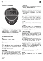
Abb. 4
3. Schritt: Montage der Griffstangensäule
Schieben Sie die Abdeckung der Griffstangensäule (13) ein Stück nach oben. Dadurch wird das vom Hauptrahmen kommende Kabel (14) freigelegt,
so dass Sie dieses Kabel (14) vorsichtig durch die Griffstangensäule (8) nach oben ziehen können. Stecken Sie anschließend das untere Ende des
Kabels der Griffstangensäule (15) mit dem Sensorkabel vom Hauptrahmen (71) zusammen. Montieren Sie dann die Griffstangensäule (8) mithilfe der
gebogenen Unterlegscheiben (5) und der Inbusschrauben (6) an den Hauptrahmen. Verbinden Sie das Kabel des Widerstandreglers (10) mit dem vom
Hauptrahmen kommenden Kabel (14) (siehe Abb. A und B), und fixieren Sie anschließend den Widerstandregler (10) mittels der großen gebogenen
Unterlegscheibe (62) und der Kreuzschraube (61) an der Griffstangensäule (8).
Step 3: Attach the Handlebar Post
Move the handlebar post cover (13) to a higher position uncovering the control wire (14). After drawing the control wire (14) through the handlebar
post (8) connect the bottom of the trunk wire (15) with the bottom of the sensor wire (71) coming from the main frame. For fixing the handlebar post
assembly to the main frame use the arc washers (5) and the inner hex pan head bolts (6). Now connect the tension controller (10) with the control wire
(14) (see pictures A and B). Fix the tension controller (10) to the handlebar post (8) using the cross pan head screw (61) and the big arc-washer (62).
Fase 3: Montaggio della colonna del manubrio
Far scorrere leggermente verso l‘alto la copertura della colonna del manubrio (13). In questo modo verrà scoperto il cavo (14) proveniente dal telaio
principale, in moda da poterlo tirare su con cautela attraverso la colonna del manubrio (8). Unire quindi l‘estremità inferiore del cavo della colonna del
manubrio (15) con il cavo del sensore del telaio principale (71). Montare quindi la colonna del manubrio (8) con le rondelle ricurve (5) e le viti a brugola
(6) sul telaio principale. Collegare il cavo del regolatore di resistenza (10) con il cavo proveniente dal telaio principale (14) (vedere fig. A e B), e fissare
quindi il regolatore di resistenza (10) con la rondella ricurva grande (62) e la vite a croce (61) alla colonna del manubrio (8).
3
ère
étape: Installation de la colonne
Tirez légèrement vers le haut la colonne (13). Cela permet de libérer le câble (14) sortant du cadre principal. Tirez-la ensuite, avec précaution, dans la
colonne (8). Raccordez l’extrémité inférieure du câble informatique de la colonne (15) au câble du cadre principal (71). La colonne (8) devra ensuite être
vissée au cadre principal à l’aide de vis à 6 pans (6) et des rondelles courbées (5). Raccordez le câble informatique du régulateur de résistance (10)
au câble du cadre principal (14) (cf. figure A et B). Fixez ensuite le régulateur de résistance (10) à l’aide de la vis à croix (61) et de la grande rondelle
courbée (62) au niveau de la colonne (8).


