Installation manual 1000H
Page 4 of 10
May 2015
INSTALL TUF
-
LITE II
®
BLADES
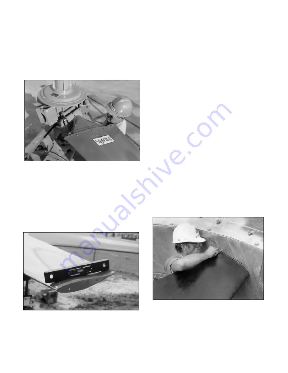
Remove blade clamp bolts, nuts, lock washers, and blade clamp
halves from hub. Assemble blade clamp halves over groove in
blade neck, and install into hub with thick leading edge to left and
thin trailing edge to right as you stand at end of blade. Install
clamp bolts through hub plates and blade clamp, putting bolt
heads on top side, lock washers and nuts on bottom (See Figure 7).
Tighten lightly.
Figure 7
SET PITCH AND TRACK
Use Hudson EXACT-A-PITCH
®
digital protractor (See Figure 8)
or a bubble protractor to set blade pitch. Mount protractor on a
flat bar as a base and place it approximately 1" from tip of blade.
Note pitch on protractor. Rotate fan 360°, noting high and low
pitch readings. Locate place where pitch reading is a mid-point
between high and low pitch readings, and set pitch at that point.
Figure 8
Rotate blade in socket until digital protractor shows specified
pitch angle to within ±0.2°. (
Fan pitch angle is shown on fan
specification sheet for design duty.)
For reverse acting hubs
(fails to minimum air flow on loss of instrument air pressure),
pitch angle should be set with 15 psi instrument signal and 55
psi supply air pressure applied (See "INSTALLING AIR
LINES").
After desired pitch angle is set, raise and lower end of fan
blade and find mid-point of blade travel. Hold blade at the
mid-point. Pull blade back so that it sits against blade clamp.
Push blade to the right to remove all slack.
Use torque wrench to tighten clamp bolts to recommended
standard of 65 ft-lb (lubricated) or 80 ft-lb (dry). Re-check
pitch setting. Blade must be set within ±0.2° of desired pitch
angle. Tighten clamp bolts evenly.
DO NOT OVER-
TORQUE CLAMP BOLTS
When bolts are tightened, hold a pencil against top end of
blade and mark the level onto a fixed object, such as a pole or
the fan ring.
Install remaining blades at same place as first blade, following
procedures above. After tightening bolts, mark top end of
each blade in same place first blade was marked. If marks
differ by 1/2" or more, adjust blade.
CHECK TRACK
After fan is installed in fan ring, outline top end of each blade
onto fan ring with a marker. The difference between levels of
highest and lowest outlines should not be more than 1/2" (See
Figure 9).
Figure 9


