1022410 – 0001 Rev. 2
5–8 Hardware installation
2.
Install the DTE interface cables onto the appropriate
connectors on the CIM (see figure 5-4).
3.
If your UMOD will be using an external clock source,
connect the cable onto the STATION CLK port (see
figure 5-4).
TC
G.703 BAL
REDUNDANCY
ESC SIGNALS
TO DTE
SD
IDI
M&C
STATION CLK
DDO
RD
TD
RC GND
RD
A
B
C
D
E F012
3
4
5
67
89
A
B
C
D
E F012
3
4
5
67
89
A
B
C
D
E F012
3
4
5
67
89
A
B
C
D
E F012
3
4
5
67
89
ESC SIGNALS
CONNECTION
UNBALANCED G.703
CONNECTION
(RECEIVE DATA)
UNBALANCED G.703
CONNECTION
(DROP-DATA-OUT)
1- TO 10-MHz FREQUENCY
REFERENCE INPUT
P2
P3
S1
S2
S3
S4
TP1
TP2
TP3
TP4
TP5
UNBALANCED G.703
CONNECTION
(INSERT-DATA-IN)
UNBALANCED G.703
CONNECTION
(SEND DATA)
RS-449, RS-232, V.35
CONNECTION
BALANCED G.703
CONNECTION
Figure 5-4
Customer interface module (CIM)
4.
Install the IF IN cable onto the IF IN port on the IF panel
(see figure 5-5 for location).
5.
Install the IF OUT cable onto the IF OUT port on the IF
panel (see figure 5-5).
IF
OUT
IF
IN
IF IN
PORT
IF OUT
PORT
Figure 5-5
IF panel
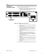
Refer to section 5.6, “Installing the multidrop cables” on
page 5–9.


