1022410 – 0001 Rev. 2
Hardware installation 5–9
This section describes installing multidrop cables between as
many as 30 Universal Modems. The multidrop cables link chassis
together to form a monitor and control (M&C) network so that
users can monitor UMOD status, and control many UMOD
functions. The multidrop cables are connected to connectors P2
and P3 on the rear of the chassis. UMOD chassis #1 is wired to
chassis #2; chassis #2 is wired to chassis #3; and so on until all
chassis are connected (see figure 5-6).
P2
P3
P2
P3
P2
P3
P2
P3
P2
P3
CHASSIS #1
CHASSIS #2
CHASSIS #3
CHASSIS #4
CHASSIS #5
MULTIDROP
CABLE
Figure 5-6
Example multidrop cable connection diagram for five UMOD chassis
5.6
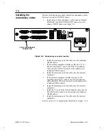
Installing the
multidrop cables


