background image


12 

 Package materials 

3004129 Revision A 


Summary of Contents for 9450 Series

Page 1: ...Hughes 9450 Mobile Satellite Terminal Installation Guide 3004129 Revision A September 15 2010 ...

Page 2: ...ort to ensure the correctness and completeness of the material in this document Hughes Network Systems LLC shall not be liable for errors contained herein The information in this document is subject to change without notice Hughes Network Systems LLC makes no warranty of any kind with regard to this material including but not limited to the implied warranties of merchantability and fitness for a p...

Page 3: ...4 Chapter 2 System power requirements 7 Fuse 7 Power cable 7 Chapter 3 Standard cable connections 9 Ignition sense white wire 9 Chassis grounding 9 Chapter 4 Package materials 11 Chapter 5 Vehicular installation 13 Basic installation procedure 13 Installation notes 13 Common IDU mounting information 14 Land mobile antenna 15 Magnetic mounting optional 15 Installation 16 Dismounting magnetically mo...

Page 4: ...iv Contents 3004129 Revision A ...

Page 5: ...Unit IDU 2 Figure 3 Inserting SIM card in the SIM card holder 5 Figure 4 Chassis ground 10 Figure 5 Common Indoor Unit mounting dimensions 15 Figure 6 C10 antenna with magnetic mount component parts 16 Figure 7 Class 10 antenna Outdoor Unit ODU 477 mm X 153 mm height 20 Figure 8 C11 antenna ODU 252 mm x 119 mm height 20 ...

Page 6: ...vi Figures 3004129 Revision A ...

Page 7: ... vii Tables Table 1 Power port pin out 2 Table 2 RJ 45 Ethernet port pinout 3 Table 3 ISDN port pin out 3 Table 4 RJ 11 port pinout 4 Table 5 System power requirements 7 Table 6 Power cable pinout 7 Table 7 Package materials 11 ...

Page 8: ...viii Tables 3004129 Revision A ...

Page 9: ...ble death read and comply with all safety alert messages Messages concerning personal injury The signal words WARNING and CAUTION indicate hazards that could result in personal injury or in some cases death as explained below Each of these signal words indicates the severity of the potential hazard WARNING indicates a potentially hazardous situation which if not avoided could result in death or se...

Page 10: ...mbol calls attention to a potential personal injury hazard It appears next to the WARNING and CAUTION signal words as part of the signal word label Other symbols may appear next to WARNING or CAUTION to indicate a specific type of hazard for example fire or electric shock ...

Page 11: ...tellite terminals are composed of four core component parts the transceiver or Indoor Unit IDU the antenna or Outdoor Unit ODU the power connector cable and an 8 meter RF cable Figure 1 Common IDU left Class 10 ODU middle and Class 11 right The Hughes IDU has multiple interfaces that various Terminal Equipment TE devices such as laptops PDA s phones etc can connect to four PoE Ethernet RJ 45 ISDN ...

Page 12: ...ection from the power supply vehicle battery or some other 12 or 24 Vdc power source to the IDU The power cable has a V power line an ignition sense line and a V power line Table 1 Power port pin out Line type Pin number V power line 1 Ignition Sense 2 V power line 3 4X RJ 45 Ethernet with Power over Ethernet PoE ports There are four RJ 45 ports with Power over Ethernet PoE on the IDU The ports su...

Page 13: ...by the PoE is limited to 30 8 W maximum for 12 V installations and 61 6 W maximum for 24 V installations The IDU automatically detects the class of the device plugged in and will apply power such that the total cannot exceed these limits If the user attempts to connect a combination of devices that require more than this the IDU will not power any devices that would cause the limit to be exceeded ...

Page 14: ... the antenna The antenna cable carries DC power do not connect or disconnect the antenna cable while the unit is powered on WLAN port The WLAN port on the IDU is a reverse polarity SMA jack The supplied antenna is a 2 4 GHz 3 dBi Rubber Duck antenna with RP SMA plug connector part number HG2403RD RSF To prevent blocking or attenuation of the WLAN signal the IDU should be installed such that there ...

Page 15: ... Introduction 3004129 Revision A 5 Figure 3 Inserting SIM card in the SIM card holder ...

Page 16: ...6 Introduction 3004129 Revision A ...

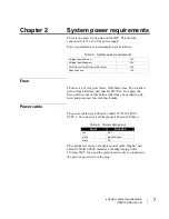
Page 17: ...blow ATO blade fuse The installed part is from Littelfuse part number 0257015 To replace the fuse pull fuse out of fuse holder pliers may be needed to grip fuse and press new fuse into fuse holder Power cable The power cable uses a Phoenix contact 1718384 PC5 3 STCL 7 62 connector and the pinout is shown in Table 6 Table 6 Power cable pinout Color Function red DC white Ignition Sense black DC The ...

Page 18: ...8 System power requirements 3004129 Revision A ...

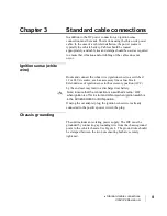
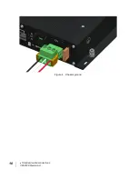
Page 19: ... to a switched 12 or 24 Vdc source such as accessory line or fuse block Extended use of ignition sense in the accessory position ACC by the end user may lead to a discharged car battery Note Ensure that the connection is a switched source OFF when ignition is off or in start and ON only when ignition switch is in the ACCESSORIES or RUN position If using the car adapter plug the ignition sense wire...

Page 20: ...10 Standard cable connections 3004129 Revision A Figure 4 Chassis ground ...

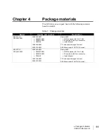
Page 21: ...97 0001 3500472 0001 3004129 1502819 0001 3500479 0001 Radio 9450 WLAN antenna 2 4 GHz 3 dB Power cable with 3 pin connector Install Manual C11 antenna with magnetic mount RG400 coax cable TNC TNC 8 meter 9450 10 kit 3500497 0002 3500462 0001 9506197 0001 3500472 0001 3004129 1502740 0001 3500479 0001 Radio 9450 WLAN antenna 2 4 GHz 3 dB Power cable with 3 pin connector Install Manual C10 antenna ...

Page 22: ...12 Package materials 3004129 Revision A ...

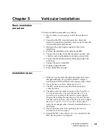
Page 23: ...Power up the IDU antenna Installation notes 1 Whenever routing cable through holes drilled in metal or through bulkheads use grommets and RTV sealant to weatherproof all holes drilled on the outside of the vehicle 2 Use cable ties every 300 450 mm 12 18 3 The IDU can be mounted in either the horizontal or vertical position 4 The main power line must be connected to a fused 12 or 24 Vdc power sourc...

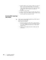
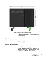
Page 24: ...o the IDU with a drip loop 10 With the exception of the IDU to antenna RF cable do not route the power cable outside the vehicle Common IDU mounting information Note Use care when drilling through the body of the vehicle to avoid puncturing critical items Instructions for the installer 1 Mount the terminal onto a flat surface using at least four screws not supplied Use screws with a diameter betwe...

Page 25: ...This section addresses the C10 antenna Procedures are the same for the C11 antenna Magnetic mounting optional Three magnetic mounts are optional for the antenna installation These mounts will withstand 100 mph wind force If the antenna cannot be mounted using the magnetic feet the magnetic feet can be removed and the mounting holes can be used to bolt the antenna onto a roof bracket system ...

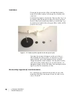
Page 26: ...e nut on top Figure 6 C10 antenna with magnetic mount component parts Now place the antenna with magnets on the roof of the car When installing the antenna cable it s important to protect against moisture using self amalgamating tape or similar wrapped around the coaxial connector Also be careful with the cable run from the antenna and secure it at short intervals An unsupported length of cable wi...

Page 27: ...sing the magnetic feet option the three mounting holes on the outside diameter of the antenna can be used to bolt the antenna onto a roof bracket system Please ensure that you utilize the proper bolt size to withstand the wind loading and vibration that the antenna will undergo for your particular application ...

Page 28: ...18 Vehicular installation 3004129 Revision A ...

Page 29: ...oth the Class 10 and Class 11 ODUs are 2 axis antennas intended for land mobile use Connection to the ODU is made by a TNC connector The single coaxial cable carries L band RX and TX power and tracking information Physical dimensions ODU Size Class 10 477 mm x 153 mm Weight 6 kg Size Class 11 252 mm x 119 mm Weight 2 kg Only use the C10 antenna supplied with the 9450 terminal Do not use the simila...

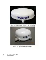
Page 30: ...20 The antenna Outdoor Unit ODU 3004129 Revision A Figure 7 Class 10 antenna Outdoor Unit ODU 477 mm X 153 mm height Figure 8 C11 antenna ODU 252 mm x 119 mm height ...

Page 31: ...na The antenna cable carries DC power Always power the IDU down prior to connecting or disconnecting the antenna cable from either the antenna or the IDU The antenna port is a 50 Ohm female TNC This line carries RF signaling and DC power for the antenna Keep a clear line of sight to the satellite Preferably avoid all obstructions within 3 meters of the antenna Obstructions less than 150 mm 6 inche...

Reviews: