Chapter 3 • Assembling and installing the antenna
1036469-0001 Revision D
15
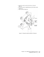
Figure 11 illustrates the difference between the horizontal
shim and vertical shim. Note the positions of the alignment
pins.
4. Remove the horizontal shim and O-ring.
5. Install the vertical shim and O-ring in the same location.
Because of its shape and alignment pins on the
transmit/receive isolation assembly (TRIA), the vertical shim
can only be installed in the position shown in Figure 11
(upper right photo). Note the position of the alignment pins.
Likewise, the horizontal shim can only be installed in one
position.
Because of the shim’s alignment pins, you must rotate the
TRIA 90 ° from its horizontal polarization position. You must
rotate the TRIA
before
you re-attach the waveguide end so
Figure 11: Horizontal shim and vertical shim for transmit polarization
TRIA
Horizontal shim in place
Vertical shim in place
(In this photograph, the TRIA
has not yet been rotated.)
Alignment
pins
O-ring
Horizontal shim
Vertical shim
Alignment
pins
Summary of Contents for AN6-074S
Page 8: ... Important safety information viii 1036469 0001 Revision D ...
Page 11: ... Contents 1036469 0001 Revision D xi Acronyms and abbreviations 49 Index 51 ...
Page 12: ... Contents xii 1036469 0001 Revision D ...
Page 16: ... Tables xvi 1036469 0001 Revision D ...
Page 18: ... About this document xviii 1036469 0001 Revision D ...
Page 28: ...Chapter 2 Antenna components tools and materials 10 1036469 0001 Revision D ...
Page 48: ...Chapter 4 Cabling and connections 30 1036469 0001 Revision D ...
Page 68: ... Acronyms and abbreviations 50 1036469 0001 Revision D ...


